


New Hydraulic Transmission Gear
Page 56
If you've noticed an error in this article please click here to report it so we can fix it.
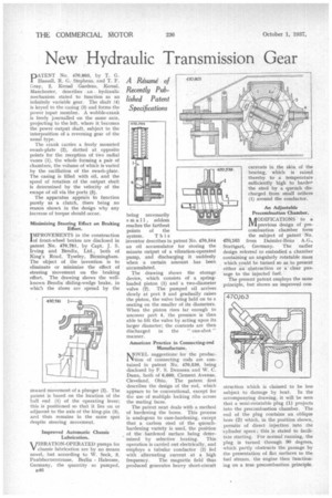
A Résumé of Recently Published Patent Specifications PA TENT No. 470,803, by T. G. Hassan, R. G. Stephens, and T. F. Gray, 2, Kersal Gardens, KersaI, Manchester, describes an hydraulic mechanism stated to function as an infinitely variable gear. The shaft (4) is keyed to the casing (3) and forms the power input member. A wobble-crank is freely join-nailed on the same axis, projecting to the left, where it becomes the power Output shaft, subject to the interposition of a reversing gear of the usual type.
The crank carries a freely mounted awash-plate (2), slotted at opposite points for the reception of two radial vanes (1), the whole forming a pair of chambers, the volume of which is varied by the oscillation of the awash-plate. The casing is filled with oil, and the speed of rotation of the output shaft is determined by the velocity of the escape of oil via the ports (5).
The apparatus appears to function purely as a clutch, there being no reason shown in the design why any increase of torque should occur.
Minimizing Steering Effect on Braking
IMPROVEMENTS in the construction of front-wheel brakes are disclosed in patent No. 470,781, by Capt. J. S. Irving and Beridix, Ltd., both of King's Road, Tyseley, Birmingham. The object of the invention is to eliminate or minimize the effect of steering movement on the braking effort. The drawing shows the wellknown Bendix sliding-wedge brake, in which the shoes are spread by the
inward movement of a plunger (2). The patent is based on the location of the hall end (1) of the operating lever; this is positioned so that it lies on or adjacent to the axis of the king-pin (3), and thus remains in the same spot despite steering movement.
Improved Automatic Chassis Lubrication. VirIBRATION-OPERATED pumps for V chassis lubrication are by no means novel, but according to W. Seek, 3, Paulsbornerstrasse, Berlin Halensee, Germany, the quantity so pumped, B46 system. This inventor describes in patent No. 470,544 an oil accumulator for storing the minute output of a vibration-operated pump, and discharging it suddenly when a certain amount has been accumulated.
The drawing shows the storage device, which consists of a springloaded piston (1) and a two-diameter valve (2). The pumped oil arrives slowly at port 3 and gradually raises the piston, the valve being held on to a seating on the smaller of its diameters. When the piston rises far enough to uncover port 4, the pressure is then able to lift the valve by acting upon its larger diameter; the contents are then discharged in the " one-shot " manner.
American Practice in Connecting-rod Manufacture.
fidOVEL suggestions for the produc tion of connecting rods are contained in patent No. 470,539, being disclosed by F. S. Denneen and W. C. Dunn, both of 6,600, Clement Avenue, Cleveland, Ohio. The patent first describes the design of the rod, which appears to be conventional, except for the use of multiple locking ribs across the mating faces.
The patent next deals with a method of hardening the bores. This process is analogous to case-hardening, except that a carbon steel of the quenchhardening variety is used, the position of the hardened surface being determined by selective heating. This operation is carried out electrically, and employs a tubular conductor (2) fed with alternating current at a high frequency. The magnetic field thus produced generates heavy short-circuit
nODIFICATIONS to a inprevious design of precombustion chamber form the subject of patent No. 470,163 from Daimler-Benz A.G., Stuttgart, Germany. The earlier design referred to embodied a chamber containing an angularly rotatable mass which could be turned so as to present either an obstruction or a clear passage to the injected fuel.
The present patent employs the same principle, but shows an improved con
struction which is claimed to be less subject to damage by heat. In the accompanying drawing, it will be seen that a semi-rotatable plug (1) projects into the precombustion chamber. The end of the plug contains an oblique bore (2) which, in the position shown, permits of direct injection into the cylinder space ; this is stated to facilitate starting. For normal running, the plug is turned through 90 degrees, which partly obstructs the passage by the presentation of flat surfaces to the fuel stream, the engine then functioning on a true precombustion principle.