


A COMPRESSED-AIR BRAKE
Page 62
Page 63
If you've noticed an error in this article please click here to report it so we can fix it.
of Continental Origin
The Knorr System of Braking for Heavy Commercial Vehicles, for which Important Marketing Arrangements are Being Made in Great Britain
rliALKING recently to Mr. Kurt
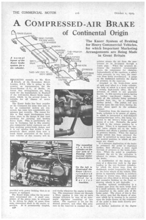
Erlach. of 32, Newcomen Street, London, S.E.1, who is acting in this country as representative for the Knorr-Bremse A.-G„ of Berlin, we learnt that arrangements. are being made for the manufacture in England of the well-known .Knorr brake equipment, which, in its several forms, is suitable for all classes of motor vehicle.
The Knorr brake has been popular on the Continent for some time and, so far as commercial motors are concerned, has come into considerable prominence just recently. The reason for this is that rapid developments have taken place in the design of fast road machines for carrying and hauling heavy loads. This is particularly the case in Germany, but in this country also commercial motor engineers are all busy studying power-brake design, and it is our opinion that within a comparatively short period from now a much larger proportion of the heavy road vehicles of this country will be
provided with power braking than is at present so equipped.
The Knorr brake relies for its power upon compressed air. A small cornpessor, of the piston type, is arranged to be driven by chain or gears from some convenient shaft in the engine or gearbox, it is permanently coupled,
and Works whenever the engine is rotating. The compressor draws air through a filter, passing it into one or more storage cylinders by way of an auto., Indic regulator consisting of two valves. The regulator is set for the desired pressure, and when this pressure in the reservoir is reached the re gulator causes the air from the corn'Pressor to be by-passed through a waste pipe. When the pressure decreases the regulator automatically resets the compressor for charging. Independently of the regulator, a safety valve prevents, in any case, the reservoir from being overcharged. A gauge on the dashboard indicates the degree of pressure in the reservoir.
Attached to the brake-drum cover of each road wheel is a brake cylinder, the body of which is a stout casting of a certain high-tensile alloy, the constitution of which is not generally known. In this operates a piston having a leather cup-shaped washer, the skirt of the cylinder being protected against dust, etc., by a collapsable leather jacket. The piston rod acts directly upon the cam lever, forcing the brake shoes apart in the orthodox manner.
Connection from the reservoir to the brake cylinders is by means of piping, in which is interposed a well-designed rotating-disc-type valve, this being connected to the driver's brake pedal by means of a rod. Normally, the pedal is held in the release position by a spring. When it is depressed the con, trol valve admits air to the brake cylinders and effects a gradual increase of pressure therein. When the desired brake actiori has been attained the pedal is permitted to move back into the neutral position, in which all passages are closed.
If a stronger application of the brake be necessary the pedal is depressed farther, thus effecting a more rapid increase of pressure in the brake cylinders. When the pedal is completely released the air in the cylinders is allowed to escape, thus withdrawing the brake.
A modification of the design consists of a three-way cock in the pipe leading to the two forward cylinders, by which the driver may, from the dashboard, render inoperative the brake on the front wheels of his vehicle. This device is especially suitable in northern Europe in winter time, when non-skid chains are often fitted to driving wheels and excessive braking on the front or steering wheels is not desirable.
Another optional modification is a by-pass pipe from the main brake lead to a small cylinder, the piston of which is connected to the under side of the brake pedal. The object of this is that the driver may feel the degree of pressure which he is causing to be exerted upon the brake drums, as the resistance of the pedal is thus made directly proportional to it.
A further indication of the degree to which the brake has been applied is afforded by a second needle in the
gauge fitted to the dashboard. As stated above, one needle indicates the pressure of air in the reservoir. The second needle indicates the pressure of air in the main pipe from the control valve to the brake cylinders, thus enabling the driver, so to speak, to -watch the brakes going on.
A feature of the system is an ingenious arr'angeinent for • a trailer brake, the object of which is that the pressure shall be employed to keep the brake in the " off" position, release of the pressure causing the brake to go
on. The result is that, should the trailer break, away from the tractor or towing vehicle, the severance of the flexible connection will result in the trailer_ brake being applied.
A provision is made to prevent the less of pressure, from the piping system of the tractor unit should such severance take place. The coupling of the flexible connection is of the type familiar in railway practice and breaks automatically without causing damage: Another ingenious point is that in the rotating-disc control valve the ports are so arranged that the trailer brakes come into action just before the brakes on the tractor and are released last.
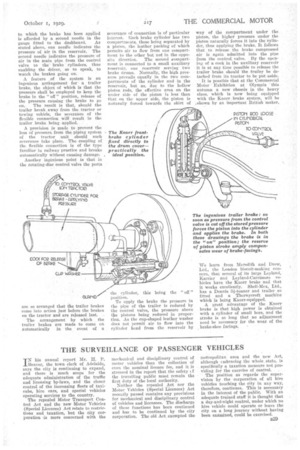
The arrangement by which the trailer brakes are made to come on automatically in the event of a severance of connection is of particular interest. lEach brake cylinder has two compartments, these being separated by a piston, the leather packing of which permits air to flow from one compartment to the other but not in the opposite direction. The second &ompartment is connected to -a small auxiliary reservoir, one reservoir serving two brake drums. Normally, the high pressure prevails equally in the two compartments of the cylinder and in the reservoir, but as, due to the hollow piston rods, the effective area on the under side of the piston is less than that on the upper side, the piston is naturally forced towards the skirt of the cylinder, this being the " off " Position.
To apply the brake the pressure in the pipe of the trailer is reduced by the control valve, the pressure above the pistons being reduced in proportion. As the cup-shaped leather washer does not permit air to flow into the cylinder head from the reservoir by way of the compartment under the piston, the higher pressure under the piston naturally forces it into the cyliiader, thus applying the brake. It follows that to release..the brake compressed air is again admitted into the pipe from the c-ontrol valve. By the opening of a cock in the auxiliary reservoir
• it is at any time possible to release the trailer brake should the trailer be detachedfrom its, tractor to be Mit aside.
It is possible that at the Commercial Motor Exhibition at Olympia this autumn a new chassis in the heavy class, which is now being equipped with the Knorr brake system, will be shown by an important British maker.
'We learn from Meredith and Drew, Ltd., the London biscuit-making concern, that several of its large Leyland, Karrier and Leyland-Carrimore vehicles have the Knorr brake and that it works excellently. Shell-Max, Ltd., has a Dennis 8i-tonner and trailer so fitted and a Thornycroft machine which is being Knorr-equipped.
A great advantage of the Knorr brake is that high power is obtained with a cylinder of small bore, and the stroke is so long that no adjustment need he necessary for the wear of the brake-shoe facings. •