


When the MGX system is working properly and powered from
Page 103
Page 104
Page 105
If you've noticed an error in this article please click here to report it so we can fix it.
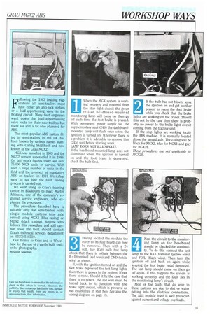
the stop light circuit the green trailer headboard-mounted monitoring lamp will come on then go off each time the foot brake is pressed. With permanent power supply via the supplementary suzi (245) the dashboardmounted lamp will flash once when the ignition is turned on. Whenever there is a problem it is advisable to remove this (24S) suzi before starting work.
LAMP DOES NOT ILLUMINATE If the headboard-mounted lamp does not illuminate when the ignition is turned on and the foot brake is depressed, check the bulb first.
Having located the module the cover to its fuse board can now be removed. Then with a 24 volt, five Watt bulb test lamp check that there is voltage between the B+I terminal (red wire) and CND (white wire) as shown.
If, with the ignition turned on and the foot brake depressed the test lamp lights then there is power to the system. If not there is none. Should it be the case that there is no power, the red wire must be traced back to its junction with the brake light circuit, which is powered as was established in step two. See also the wiring diagram on page 18.
3
If the bulb has not blown, leave the ignition on and get another person to press the foot brake while you check that the brake lights are working on the trailer. Should this not be the case then there is prob-' ably no power to the brake light circuit coming from the tractive unit.
If the stop lights are working locate the ABS module. It is normally located above the sensed axle. The casing will be black for MGX2, blue for MGX1 and grey for MGX2E.
These procedures are not applicable to MGA2E.
2
Next the circuit to the monitoring lamp on the headboard should be checked for continuity. To do this connect the test lamp to the B+L terminal (yellow wire) and FO/L (black wire). Then turn the ignition off and back on again while keeping the foot brake pedal depressed. The test lamp should come on then go off again. If this happens the system is working correctly and the fault lies in the monitoring lamp's circuit.
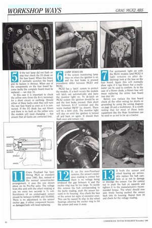
Most of the faults that do arise in these systems are due to dirt or water getting into the electrical connections. The ABS module itself is well protected against current and voltage overloads. If the test lamp did not flash on step four check the D3 diode on the fuse board. When this blows it normally scorches the board and its faulure is obvious. When any of the components on the fuse board become faulty the complete board must be replaced — see step 14.
In this case it is important to check the yellow wire (from the B+L terminal) for a short circuit or earthing. Should either of these faults exist they will ruin the new fuse board as soon as it is connected. If the D3 diode has not blown and there is no fault on the yellow wire the module will need changing — but ensure that all faults are corrected first. If the system monitoring lamp stays on when the ignition is on and the foot brake is pressed procedures differ between MGX1 and MCX2.
MGX2 has a 'latch' system to protect the module. If a fault occurs the module will latch out automatically and leave the monitor light on. To de-latch an MGX2 system the ignition should be on and the foot brake pressed, then short out between B+F terminal and the screw marked FR/TP (as shown). There will be a faint click. The monitor light will stay on until the ignition is turned off and back on again. It should then flash once and remain out.
7 For permanent light on with
the MGM module (and MGX2 if light remains on after de latching) look at the fuse on the fuse board. Again this will normally show signs if it has blown but a multimeter can be used to confirm. As in the case of a blown diode, a blown fuse will mean replacing the entire fuse board (see step 14).
Before you replace the fuse board check all the other wiring for shorts or grounding by using the wiring diagram on page 18 and a multimeter. It is worth noting that for most of these tests equipment like the Hope Scrutineer can be used so as not to tie up a tractor. If the fuse has not blown and gives a positive continuity reading on the multimeter, check for the black wire from the FO/ L terminal going to ground (earthing). To do this remove the wire from its terminal. If the system monitoring lamp remains lit then the black wire has earthed, if it goes out the module will need replacing.
Only MGX2 modules and fuse boards are now available. The MGX2 module is a direct replacement for the MGM. However the MGX2 module has a different bar jumper to MGX1. Regardless of which fuse board is fitted, the MCX1 module requires a dog-legged bar jumper and the MGX2 a straight one. LAMP ON, OFF AND ON AGAIN WITHIN 3 SECONDS This denotes an open circuit or solenoid fault in the Memory
Controlled Emergency Relay (MCER) valve. To check solenoid switch the ignition off and connect a jump lead between the 13+1 terminal (red wire) and the TOP air valve terminal. Connecting to the lower terminal will destroy the module. Depress the foot brake and turn the ignition on. The valve should exhaust, if it does not replace it. Do not leave jump lead on for longer than 10 seconds with the ignition on. MGX2 units will now need de-latching again (step six). If the monitoring lamp remains on replace module (MGX1 or 2). 10 LAMP STAYS ON ABOVE
24km/h WITH BRAKES ON This indicates a sensor 24km/h WITH BRAKES ON This indicates a sensor fault. Jack up the sensed axle and connect a multimeter to the LR sensor terminals (extreme top left). Turn the left hand wheel once every two seconds. One volt AC should be registered (except on Crane Frushauf trailers: See 11). If there is no reading connect the meter to the RH terminals in case of crossed wires .
If there is still no reading remove the sensor wires from their terminals on the module and check the resistance: Above 6,000a — sensor damage/broken wire; 6,000a to 3,50011 sensor and wire OK; below 3,500S/ — damage/short.
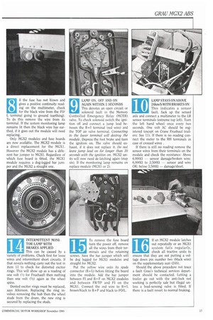
fitting MGX as standard since 1983. But, instead of the normal sensor/exciter arrangement, it uses the one shown above on its Pro-Par axles. The voltage from this unit with the wheel rotating at one rev every two seconds is 1/2 volt. Resistance of an undamaged sensor should be between 6,000.12 and 10,00011 There is no adjustment to the sensor/ exciter gap, if either component becomes damaged both will need replacing. systems, the sensor's resist ance reading is correct but there is no voltage being produced the gap between it and the exciter ring may be too large. To rectify this remove the hub corresponding to the faulty reading, push the sensor forward in its housing. Also check the face of the sensor for signs of excessive wear. This can be caused by play in the wheel bearings allowing the exciter ring to hit the sensor and wear it away.
13 If both the sensor and
wheel bearing are service able replace the hub care fully so as not to damage or dislodge the sensor. Use the central nut to push the hub on squarely and tighten it to the manufacturer's recommended torque. The wheel should now spin freely having pushed the sensor back into its housing. Repeat item 10 and check for the voltage reading. TOR LAMP WITH BRAKES APPLIED This can be caused by a variety of problems. Check first for loose wires and intermittent short circuits. If that reveals nothing carry out the test in item 11 to check for distorted exciter rings. This will show up as a reading of one volt (1/2 for Fruehauf) then nothing then one volt (1/2) again as the wheel spins.
Dented exciter rings must be replaced, says Atkinson. Replacing the ring involves removing the hub then the wheel studs from the drum, the new ring is secured by replacing the studs. turn the power off, remove all the wires from their ter
15 To remove the fuse board
turn the power off, remove all the wires from their ter minals and the retaining screws. Save the bar jumper which will be dog legged for MGX1 modules and straight for MGX2.
Put the yellow wire onto its spade connector (B+L) before fitting the board into the module. Add the bar jumper between FI and B+F on MGX2 modules and between FR/TP and F1 on the MGX1. Connect the red wire to B+1, brown/black to B+P and black to FOIL. out repeatedly or an MGX1 system fails regularly, check all tractive units to ensure that they are not putting a voltage down pin number two (black wire) on the supplementary suzi (245).
Should the above procedure not trace a fault Grau's technical services department should be contacted. Letting a trailer go out with the anti-lock not working is perfectly safe but illegal unless a load-sensing valve is fitted. If there is a fault revert to normal braking.