


Test benches A range of Merlin Calimaster fuel-pump test benches
Page 55
Page 56
If you've noticed an error in this article please click here to report it so we can fix it.
offers variations on the number of cylinders and hp in both mechanical and hydraulic infinitelyvariable-speed drives using the same basic construction in a standard frame.
The full range available is: 8or 12.-cylinder hydraulic drive of 71, 10 or 15 hp; 8or 12 cylinder mechanical drive of 7 and 10 hp; all retaining the Merlin principle providing a lowspeed high-torque drive. The hydraulic drive machines nave spindle speed ranges of 0-5,000 rpm and 0-1,300 rpm.
The mechanical drive machines have spindle speed ranges of 45-600 rpm and 360-5,000 rpm on 50 cycles and 50-725 rpm and 480-6,000 rpm on 60 cycles. Change of speed-range is by hand-operated lever and change of speed within the range by push-button rile torized control. For fine adjustment of speed and for running over a governor an overricin,j manual speed control handwheel is provided. The inertia of the rotating parts solidly connected to the drive shaft is sufficient to provide a drive substantially free of cyclical speed variations.
The drive shaft and bearings are adequately proportioned to withstand the stresses set up. as in fact is the whole of the structure.
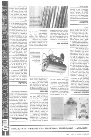
The fuel system contains a 10 Imperial gallon (12gal US— -45 litres) fuel tank incorporating a strainer and magnetic filter. has been designed to provide from separate outlets, fuel a7 high pressures (up to 500 psi.) for phasing and low pressures for calibrating. Provision is made for an electrical fuel heater, thermostat and thermometer. For easy, accurate reading the pressure gauges are 4in. diameter and cover 0-600 psi., 0— 2 000 p.s.i. and 30in.Hg 0 60 psi. The latter gauge is piped internally to the calibrating fuel supply giving an accuracy of feed pressure hitherto unknown in fuel pump testing and enabling suction tests to be performed merely by the closing of a valve.
Filtration is by a replaceable cartridge-type filter (5 microns) of large capacity and low suction restriction, situated in the supply line to the gear pump. Because of the danger of contamination of the test fluid by lubricating oil, etc., bed drainage is provided by a separate waste tank.
" Optional extras in the fuel circuit are available as follows:— Connections are built into the machine to allow fitment of the secondary filter to the fuel circuit between lift pump and injection pump (a common requirement of American fuel-injection equipment manufacturers). An extra sensitive low feed-pressure regulating device is included to provide a condition where, for instance, distributor-type pumps may be fed at a pressure of 1 psi. regardless of speed and delivery.
The Shot-counting system fitted comprises a series of relays and solenoids and provides multiples of 100 up to 2,000 injections.
The whole of the test bench is readily accessible by the removal of side panels and a cowl over the drive pulleys (which also serves as a double-sided writing desk). All the features described above are embodied in the test benches as improvements to cater for existing and future test principles.
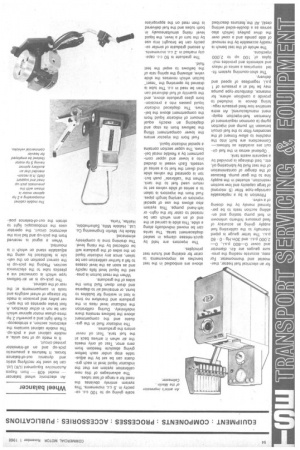
The injectors are held by quick-release clamps in sealed displacement tanks. The tanks can be moved individually along a slide. This slide is carried at the end of an arm which can be rotated to cater for the rightor left-hand pumps. This system also allows the use of special injectors or varying length pipes. Fuel from the injectors is taken to a series of slide valves set to return used fuel to the tank. When the "calibrate" push button is operated the valves slide and divert the fuel to a series of vessels. Each vessel is divided into a lower and upper compartment by a flexible metal bellows. The upper section contains a special indicator liquid.
Fuel from the injector enters the lower compartment lifting the bellows from its stop and displacing an exactly equal amount of indicator liquid from the compartment above the bellows. The displaced indicator liquid passes into a precisionbore glass graduate above, and the quantity of fuel delivered can then be read in c.c. The tube is drained by operating the "reset" button which reverses the slide valve, allowing the spring rate of the bellows to expel the test fluid.
The graduate is 50 c.c. capacity marked in .2 c.c. increments. A second graduate of similar capacity can be brought into use by the turn of a lever, the liquid level rising simultaneously in both tubes and the fuel delivered is then read on the appropriate scale giving up to 100 c.c. capacity in .5 c.c. increments. This system entirely obviates the need for a range of test tubes.
The advantages of this new calibration system are that the indicator liquid level in each graduate can be set by the adjustable stop under each bellow giving absolute freedom from zero error. Test oil only meets the air when it arrives back at the fuel tank. Test oil never enters the graduates.
The indicator fluid in the graduate and the compartment above the bellows remains there indefinitely. During calibration the indicator level rises in the graduate and therefore no time is lost in waiting for bubbles to burst, or entrained air to disperse and drain down fluid from the sides of the graduate.
When the reset button is pressed the liquid level falls rapidly and as soon as the level ceases to fall a further calibration can be taken, since any indicator liquid on the sides of the graduate will be collected by the rising level. The draining time is completely eliminated.
Made by: Merlin Engineering Co. Ltd., Hebble Mills, Salterfiebble, Halifax, Yorks.