


FRICTION TRANSMISSION GEAR.
Page 32
If you've noticed an error in this article please click here to report it so we can fix it.
A Résumé of Recently Published Patents.
The leading patent this week refers to change:speed •gear which is frictionally operated. It is of the type in which power is transmitted from a smooth conical drum to one or a pair of driven shafts, which are an arranged that their axes are parallel with the surface of.the drum. These two shafts • carry friction discs which come into contact with the sides of the drum and thus trinsmit the power.
Readers are most likely to be familiar with that type of friction gear in Which the driving disc is at right angles to the driven one. In inch a case, wherever the driven discs or, at least, that disc with the friction material round its edge, is in cottact with the driver or face of another disc, a certain amount of lost motion must occur across the width of its rim, as only one point across the width can be travelling at the same speed as the surface of the disc with which it, is, for the time being, in contact. Over the remainder of the width a certain amount of slipping, involving loss of power and wear of the material of which the disc is made, must take place. This is claimed to be avoided la the gear which is the s subject of qist'spreseat patent.
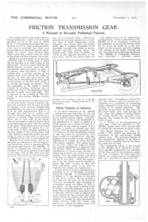
The present invention comprises a conical friction drum, having, a smooth surface and arranged with its apex towards the engine. It is, however, displaceable longitudinally by means of a pedal, and it is by this displacement that it is brought into and out of contact with t he four friction discs, thus serving' in a manner as a clutch. There are two driven discs, outs at each side of the drum; they are mounted on splined shafts which are permanently parallel with the surface of the drum. These shafts are so arranged that, when coupled by means of a universal joint to bevel gearing mounted in the rear wheels of the vehicle, they, with their respective propeller shafts, are normally in line, so that there is little loss of efficiency from lack of such alignment. Details of the construction will be understood by reference to the accompanying illustration, which is reproduced from the patent, specification (No. 169,006). It should be pointed out, however, that a socketed or cut-away portion is provided at the apex -end of the gone, and this serves as the neutral or free-engine pod.
tion for the driven discs. 'Moreover, beYond the cut-away portion is a secondary cone, of small dimensions which .ordinarily runs freely upon the engine shaft, and is actually connected to an internally toothed ring which is driven through epicyclic gearing from the engine shaft. This cone, therefore, revolves in the opposite direction to the main cone, and if the driven discs are
Other Patents _of Interest.
J. D. 1-toots describes in No. 169,010 a carburetter and vaporizer, by the aid of which naphthalene may be used as fuel for an ordinary petrol engine. Actually, the device described and illustrated in the specification is shown, as fitted to a Ford, though, as a matter of fact, it is applicable to any type of engine. A box or. tank is bolted or clipped into close contact with thesexhaust manifold. This is a container for the naphthalene, which, in use, must first be converted by heat from a solid to a, liquid form. Its temperature must be still further raised and maintained at a point at which the fuel will readily vaporize. The engine draws its air from within the tank, in which the melted naphthalene is disposed, and the device which is described in this specification is particularly devised to ensure the indrawn air coming into close contact with the naphthalene, and thus collecting an adequate proportion of it so that it will burn. With the apparatus in use the engine must be started on petrol and kept running on that fuel Until sufficiently warm to be ab'e to vaporize and accept the naphthalene. A neat form of circular splaShguard is described by F.' J. -Hundleby in, specification No. 169,124. A falseahol-low hub is bolted on to the exterior Of the 1-tub of the wheel, and to this is secured a steel plate in the form of the frustrum Of a cone, its exterior edge extending to a diameter about two-thirds of that. of the wheel. To this again is bolted a disc of rubber or flexible material, so that the outer edge of the latter comes quite close lo the tyre, and also close to the ground. it is claimed by the inventor that mud which would be thrown by the wheel laterally is caught by this splashguard, which revolves with the wheel, and thrown, as regards its greater part, into the interior of the mudguard. The improvement to an internal-ex panding brake, which is described in No. 169,067, by P. J. Goodman, consists in theutiiization of an annular spring which fits all round the brake in a"slot pro, vided f or the purpose, and also engages with notches in the brake fulcrint and cam, thus preventing sideways movement No. 169,035, by Caterpillar Tractors, Ltd., describes a governor control
throttle valves According to this inven_ tiott the throttle valve is formed as a weighted cone, preferably of streamline shape, adaptesi to close upon a bevelled seating in the intake manifold. The governor is connected to this valve by the -usual links, pins, and springs, so that, when the engine is running below its normal speed, the governor overbalances the weight of the valve and holds it open.
J. L. Norton, in the arrangement of valve gear which he describes in No. 169,041, makes both valve springs help to control the movement of either valve.
The Marks steering Co.; Ltd. describe in No. 169,011 an improved arrangement of the well-known Merles steering gear. The principal feature of the construction appears to be that it allows of two complete turns of the steering wheel for one lock.
The carburetter which is the subject of No. 169,027, by J. Bamford, is actually a paraffin carburetter, but embodies atthe outer end of the air inlet a priming Cilia, whereby, for the , first few strokes, the engine may be compelled to 'take, up a mixture of petrol and air.