


W. — Adjusting Fan on 2 - ton Napier.
Page 30
Page 31
If you've noticed an error in this article please click here to report it so we can fix it.
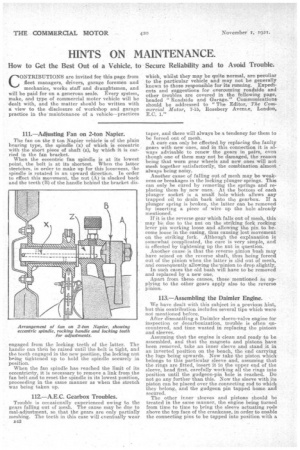
The fan on the 2ton Napier vehicle is of the plain bearing type, the spindle (x) of which is eccentric with the short piece of shaft (a), by which it is carried in the fan bracket.
When the eccentric fan spindle is at its lowest point, the belt is at its shortest. When the latter stretches, in order to make up for this looseness, Ile spindle is rotated in an upward direction. In order to effect this movement, the nut (A) is slacked back and the teeth (B) of the handle behind the bracket dis
engaged from the locking teeth of the hatter. The handle can then be raised until the belt is tight, and the teeth engaged in the new position, the locking nut being tightened up to hold the spindle securely in position. When the fan spindle has reached the limit of its eccentricity, it is necessary to remove a link from the fan belt and to reset the spindle in its lowest poaition, proceeding in the same manner as when the stretch was being taken up.
112.—A.E.C. Gearbox Troubles.
Trouble is occasionally experienced owing to the gears falling out of mesh. The cause may be due to mad-adjustment, so that the gears are only partially meshing. The teeth in this ease will eventually wear
n42 taper, and there will always he a tendency for them to be forced out of mesh.
A cure cart only be effected. by replacing the faulty gears with new ones, and in this connection it is always advisable to renew the gears in pairs, even though one of them may not be. damaged, the reason being that worn gear wheels and new ones will not mesh together satisfactorily, the combination almost always being noisy. Another cause of falling out of mesh may be weakneas or breakages in the locking plunger springs. This can only be cured by removing the springs and replacing them by new ones.. At the bottom of each plunger socket is a small hole which allows any trapped oil to drain back into the gearbox. If a plunger spring is broken, the latter can be removed by inserting a piece of wire up the hole already mentioned.
If it is the reverse gear which falls out of mesh, this may be due to the nut on the striking fork rocking lever pin working loose and .allowing the pin to become loose in the easing, thus causing lost movement on the striking fork. Although the explanation is somewhat e Tr) licated, the cure is very simple, and. is effected by tightening up the nut in question. Another cause is that the reverse pinion bush rnay have .seized on the reverseahaft, thus being 'forced out of t6 pinion when the latter is slid out of mesh, and consequently allowing the pinion to drop slightly.
In such cases the old bush will have to be removed and replaced by a new one.
Apart from thesecauses, those mentioned as applying to the other gears apply also to the reverse pinion.
113.—Assembling the Daimler Engine.
We have dealt with this subject in a previous hint, but this contribution includes several tips which were net mentioned before.
After dismantling a Daimler sleeve-valve engine for inspection or decarbonisation, trouble is often encountered, and time wasted in replacing the pistons and sleeves. Assuming that the engine is clean and ready to be assembled, and that the magneto and pistons have been removed, take an inner sleeve and stand it in an inverted position on the bench, the en-d carrying the lugs being upwards. Now take the piston which-belongs to this particular sleeve and, assuming that the rings are fitted, insert it in the upper end of the sleeve, head first, carefully working all the rings into position until the gudgeon-pin hole is reached. Do not go any further than this. Now the sleeve with its piston can be placed over the connecting rod to which they belong, and the gudge.on pin tapped home and secured. The other inner sleeves and pistons should he treated in the same manner, the engine being turned from time to time to bring the sleeve actuating rods above the top face of the crankcase, in order to enable the conne.cting pins to be tapped into position with a
soft hammer. The assembling of the engine can now be completed without further trouble, as, if the inner sleeves are raised to their full limit when the heads are being replaced, there is nothing tofear. To replace the magneto, turn the engine until No. I cylinder is under compression. This can be ascertained by placing the thumb in the plug hole. Now turn the flywheel until the top dead centre is reached, reverse the engine 51, ins, on the flywheel face and make a mark on the latter ; now go farther back still and come forward again to this mark. If the arma
ture of the magneto can be seen, set it in. from the pole shoes and couple it to its timing pinion. This will providing the carburation is correct, give easy starting without the danger of violent back-firing. Incidentally, the firing order for wiring up is I, 2, 4, 3.