


FORD VAN POINTERS.
Page 26
Page 27
If you've noticed an error in this article please click here to report it so we can fix it.
By R. T. Nicholson (Author of "The Book of the Ford ").
ALIVERPOOL reader is in trouble with his switch wiring. He has taken over a van from a former driver, and finds things in a pretty -pickle. All his switch terminal connections hn,ve been shuffled, with the idea, it would seem, of using magneto current for lighting. (As this current was used for lighting on the old model, it might quite well seem to be a good idea so to use it on the new model: but it will not do—for reasons.which I will presently state.) 403.—Rectifying a Mixed Switch.
Let 116 first set things right by showing exactly how the switch shmld be wired up.
When wiring it is important that the battery should be out right out, because, in course of the job, it is likely that every now and again false battery circuits may be made (unless the battery is put out of commission), by touching together two wires that properly de not belong to the same circuit, and then bad damage may be done.
It is enough to take one of the two battery leads off its battery post; but to make doubly sure, I believe in taking both off, and so placing them, or so insulating them, that no circuit can possibly be set up. This means setting their metal clamps away from any conductor, preferably binding them with rubber, so that electrical contact may be absolutely prevented.
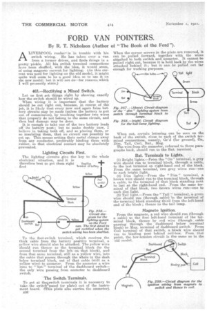
Lighting Circuits First.
The lighting circuits give the key to the whole electrical situation, and it is
therefore best to get them right Positive
first ferminol of battery
Fig. 256.— Circuit diagram for the lighting system on the Ford van. The first detail to get rectified when the switch wiring has been shuffled.
To the foot-switch terminal, which receives the thick cable from the battery positive terminal, a yellow wire should also be attached. The yellow wire should run thence to the terminal block (to the second terminal from the left on that block), and from that same terminal, still as a yellow wire, into the cable that passer, through the whole in the dash below terminal block, out of that cable (still as a yellow wire) to ammeter. From the ammeter a wire runs to "bat." terminal of the dashboard switch— the only wire passing, from ammeter to dashboard switch.
The Switch, Terminals.
To get at thekswitch terminals it is necessary to take, the switch' panel (or plate) out of the instrument board. (This plate also carries the ammeter). B36
When the corner screws in the plate are removed, it can be pulled forward, together with the wires attached to both switch and ammeter. It cannot be pulled right out, because it is held back by the wires attached behind it; but it can be pulled out far enough for working purposes.
When out, certain lettering can be seen on the back of the switch, close to each of the switch terminal connections, namely, Gr'd (for ground), On, Dim Tail, Coil, Bat., Mag.
The wire from the ammeter, referred to three paragraphs back, should run to the Bat. terminal.
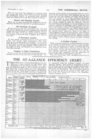
Bat. terminals to Lights.
(1) Bright lights.—From the "On " terminal, a grey wire should. run to terminal block, through a, cable, to the last terminal on right-hand end of the block. From the same terminal, two grey wires run—one to each bright light. (2) Dim lights.—From the " Dim " terminal, a brown wire should run to the terminal block, through a cable, to the terminal of that block standing next to last at the right-hand end. From the same terminal of that block, two brown wires run—one to each dim light. (3) Tail light.—From the " Tail " terminal, a green wire should run (through cable) to the terminal of the terminal block standing third from the left-hand end of the block ; thence to the tail lamp.
Magneto Ignition.
From the magneto, a red wire should run (through a cable) to the first left-hand terminal of the terminal block, thence by red wire (through cable passing' through the dashboard below terminal block) to Mag. terminal of dashboard switch. From Coil terminal of that switch, a black wire should rim to binding Post behind coil-box. From that point, the low-tension circuit is the same as in the old model. The red wire from the magneto to terminal block also serves the horn; but it does not pass through the dashboard switch.• It proceeds from terminal block as a black wire to the horn with or button.
Starter and Charging Circuits.
These do not pass through the dashboard switch, and may therefore be ignored for present purposes.
All Terminals Occupied.
If you wire in the way described, you will find that all the dashboard switch terminals are occupied except the ar'd (ground or earth) terminal. Do not worry over that : it is not meant to be occupied: it is merely a survival from a bygone time when it was used
A Necessary Caution.
All the switch terminalstmust be well and truly wired, with bright, tight connections. The wires must on no account touch one another. It is best to strip off only so much of the insulation of each wire as will allow you to bind tightly. There should be no length of bare, uninsulated wire standing away from any terminal.
Dangers of False Connections.
If you so wire the switch that wrong through connections can be set up, you may do big damage. For instance, if the wiring is so arranged that, by movement of the switch lever, the magneto can get connected up with the battery, you may easily demagnetize its magnets. Or if the Wiring is such that you can connect up your magneto with the lights, you will at once burn out your bulbs, as they are not strong enough to take the magneto current. Theoretically and actually, it is still possible to use magneto current for lighting, and I could tell you how to wire for it; but I am not going to do •so, because you would probably get things badly mixed, and do a lot of •damage: besides, you would have to get special bulbs: moreover, there is no sense in using magneto current for the purpose, when battery current does the job so much better : finally—on this point—the use of battery current for lighting steadies the battery, which, within reason, is better working than idling. •
A Further Caution.
While you are wiring up, or disconnecting wirings, at the switch, do not run the engine on any account. Wait until everything is in place—including-the two main battery lead's that I advised you to take off at the start. If you run the :engine with no connection between generator and battery, you can do bad damage—and remember that the connection is broken with either of the battery leads off. (Fig. 247—issue Sept. 27th—should•.b.e,referred to.)