


A HANDY RUNABOUT ELECTRIC CRANE.
Page 17
Page 18

If you've noticed an error in this article please click here to report it so we can fix it.
A New Utility Truck Incorporating Many Ingenious Features.
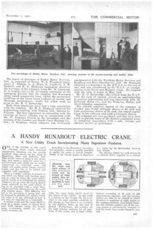
0 NE of the exhibits at this year's Olympia Show which attracted considerable attention was the electric runabout crane shown on the stand of Ransomes, Sims and Jeff eries, Ltd. This mobile crane is quite a new invention, and meets a long-feltwant for a self-contained unit which can be readily manceuvred in restricted areas and which will enable motor lorries, railway trucka and the like to be loaded and unloaded with expedition. There are motor vehicles at present in use which are fitted with hoisting gear, and in order to make the csane stable, and to enable it to withstand the strains which are set up when the load is slewed round relatively to the road wheels, it has to be provided with a large base, which naturally encroaches'on the available loading space. This difficulty has led to the provision of spraga that can be dropped to stabilize the vehicle whilst the crane is in use, although at best it can only be regarded as a makeshift. A mobile crane and the crane which is fixed on a' steam wagon or petrol lorry both fulfil definite needs, the former being particularly suited for use at jocks, markets, etc.
According to the Ransomes' invention, the turntable, which is usually provided to enable the crane to swivel independently of the chassis frame, is dispensed •
with, the crane being rigidly fixed to the chassis of the vehicle. As the crane is a fixture on the chassis, the jib is always in the same positien relatively to the chassis, so that there is no variation in the stability factor as thq load is slewed. Furthermore, the pressure on the road remains constant for all positions of the crane, and is kept within
low hunts by its distribution betWeen fear wheels.
The driving wheels are each driven by an electric motor supplied by a storage
battery consisting of 20 cells of 258 ampere-hernia cipacity, and the steering wheels are able to: be rotated in either direction to positions at right angles to the running positions. Just before reaching this extreme position one of the sunning motors is automatically reversed so that the truck then rotates about its own axis.
The lifting capacity of the crane is 15 cwt.., although the appliance is capable of sustaining an overload test of 25 per cent. The operations for the control of the crane and the truck itself are carried out by thedriver, from one position, around which' all the operating levers are conveniently, grouped.
As giving some idea of the compact construction of the little truck, we wauld mention that its overall -width does not exceed 6 ft., and, moreover, that when the jib is lowered into the horizontal position it will readily pass under a 7 ft. 6 in. doorway. The truck will also
rotate in a 6 ft. 3 in. diameter circle. The travelling speed of the truck is about 31m.p.h., its hoisting speed being 20 ft. per minute, and its slewnig speed
r.p.m.
The jib is so designed as to clear the lead when hoisted to the lull height allowed, and the weight is so disposed that with the jib fully loaded and in position the maximum weight on any one wheel never exceeds 1 ton.
The control of the Ransomes runabout crane is extremely simple, and for oidinary travelling purposes the truck is similarly operated to a motor lorry, a
directional controller placed on the right-hand side of the driver being operated by a lever working in a gate, -which is interlocked with the left pedal which controls a resistance drum, and only by depressing the pedal control which breaks the circuit can the controller handle be placed in the forward or reverse position. By releasing the pedal, circuit is made through: ,a series of resistance steps, which gosern the speed of the vehicle. The brake pedal actuates two compensating brake bands working on drums keyed on the motor spindles, and these brakes can be used either as service or ratchet brakes.
Slewing is accomplished by turning the steering wheel and lifting a pawl on the top of the master controller, the steering wheels, both front and rear, being turned and locked at right angles to the driving wheels. By operating a lever and the pedal, a clockwise or anticlockwise rotation of the crane can be obtained.
The crane controller, which is used for hoisting or derricking is placed on the left of the driver, and is operated by' a lever, working in a gate, which controls the raising or lowering of the hook. The clerricking motion of the jib is controlled by the same lever, and the mechanism is so arranged as to obtain an approximately horizontal movement of the load; thatis to say, when' lifting the jib, the hoist rope is paid out, and when lowering the jib the rope is wound back on to the hoisting drum.
It will thus be gathered that the slewing, hoisting, and derricking operations can be performed at the same time and from one position.
This crane truck was devised by Mr. P. A. Moasay, of Mossay and Co., Ltd., and is manufactured by Ransomes, Sims and Jefferiea, Ltd., at Ipswich, the crane mechanism being a new production of Ransomes and Rapier, Ltd., the well-known crane specialists of Ipswich. It is undoubtedly a very useful little machine, possessing vast potentialities; in certain fields of activity. A heavier crane truck with a lifting capacity of 35 cwt. is also being made by the company, and, although the same principles are incorporated in its design, it is of slightly different construction.