


Steel Balls as Pressure Source in Centrifugal Clutch
Page 36
If you've noticed an error in this article please click here to report it so we can fix it.
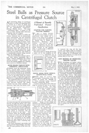
AN interesting design of centrifugal clutch, in which the operating force is created by a mass of small steel balls, is shown in patent No. 543,549 by the Borg-Warner Corporation, Chicago, Illinois, U.S.A. The name " mechanical fluid" is given to the mass of balls, because their behaviour resembles that of a liquid.
We illustrate a clutch in which the friction elements are of substantially usual construction, but the actuating means are novel. There is a groove in the flywheel, which houses a mass of metal balls or shot (2) and these, under the influence of centrifugal force, tend to move outwards. Acting like a liquid, they create pressure in all directions, but it has been found by experiment that the provision of an angular face (1) transforms the radial force into an axial one, and results in a considerable pressure being exerted upon the sliding plate (3).
The size of the balls is about 1/16 in. and they behave practically like a liquid, without presenting any serious sealing problems. The patent also shows the scheme applied to a rofating mass used as a vibration damper.
QUICK BRAKE TAKE-UP WITH POWERFUL APPLICATION
COMING from the Hydraulic Brake Co., Detroit, Mich., U.S.A., patent' No. 643,330 describes a device by which the operating pressure of an hydraulic brake system is automatically increased so soon as the shoes touch the drums, giving, in effect, a high-speed approach followed by a high-pressure application.
The apparatus shown in the drawing is intended to be incorporated in the main pipe-line between the master cylinder and the wheel cylinders. In operation, fluid from the master cylin der,enters the pipe (7) and at first flows directly through the device, b a path comprising a* port (1) in a large piston (8), a cross-bore (5) and a passage (2).
When the pressure reaches a predetermined maximuni, the spring (4) of the larger piston is overcome, and the piston is forced to the right. This movement closes the through passage by means of a valve (6) and thereafter the pressure is received by the large piston (8), transmitted to the smaller piston (3) and imparted by it to the outflowing fluid, with a resulting stepup in pressure.
The small innermost cup-washer and spring prevent fluid leakage, and maintain the open position of the valve (6).
TOgive a choice between spudded land wheels, or pneumatic-tyred road wheels for a tractor is the object of an adaptor shown in patent No. 543,519, by E. Shanks and J. Heeps, 29, Mannerston, Blackness, West
Lothian. The need for such a device is explained by the fact that if the alternative wheels were bolted directly to the existing hubs, it would cause a difference in the width of track.
The device used is a flange (2) having a spigot (4) for the reception of the road-wheel (1) to which it is secured by bolting. The inner bore (3) of the flange is tapered for the reception of a split sleeve which grips the axle when forced inwards by a bolted-on end cap. 545.618 PISTON RINGS WITH CONICAL GROOVE-WALL FACES
PISTON rings of other than rectangular cross-section form the subject of patent" No. 543,648 by A Crisp, Cornwall Lodge, Cornwall Gardens, Cliftenville, Kent.
A section of the piston skirt with two rings in position .is seen in an accompanying drawing. The rings, in this case, are shaped as part of a cone, whilst another scheme is shown in which they are a section of a sphere. In both instances the intention is the same, namely to permit the vertical working pressure to create a horizontal component which increases the sealing effect on. the walls of \ the cylinder. Rings of this design are claimed to be specially beneficial in the case of badly worn cylinders.
Alternative forms are also detailed in the specification, one being a three-piece ring, each unit having a virtually triangular section, and another a cone-shaped laminated unit made up of four thin rings. We suggest that a ring* of this design can have freedom of movement in its groove only so long as it remains perfectly concentric with the piston. A radial force on the ring, as applied by the cylinder wall, if acting at one point, would tend to contract the ring all the way around, and might result in excessive groove wear, ring breakage or scoring of the cylinder or, if concentric contraction were achieved, in a loss of the sealing effect of the ring.
NEW METHOD OF PRODUCING HOLLOW VALVES
THE advantages of hollow valves, either empty or salt-filled, are fully realized in the industry, but the manufacturing processes may, on account of their complexity, militate against the general adoption of such valves. An attempt to simplify the operations involved is shown in patent No. 543,573 by Thompson Products Incorporated, Cleveland, Ohio, U.S.A. The patent covers both the methods of naanufactire, and the valves produced thereby.
A plain cylindrical tube of steel (4), closed at' one end, is placed in a split die (3) the interior of which is formed to the desired shape of head. A filling mass (2), which may be graphite, grease, copper or one of many different substances, is placed in the bore, after which the ram (1) of a press is forced in. The effect is to expand the head into the required shape, after which the valve is taken from the die and the stem drawn out by orthodox methods, so that it ultimately appears as shown. at 5. In an alternative final form, the valve stem is hollow as well as the head. In such case, the filling mass (2) will be a cooling material such as salt or sodium and will only partly fill the space.