


TRACK-LAYING DEVELOP
Page 26
Page 27
Page 28
Page 29
If you've noticed an error in this article please click here to report it so we can fix it.
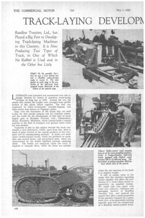
LIFEBOATS were launched and manceuvred over soft or shingly beaches by means of primitive, track-laying carriages as long ago as 1879. Around the two big wheels that carried the weight were arranged loose girdles formed. of fiat plates linked together. The idea was originated by Lieut.-Commander Gartside-Tipping, and these -tracks were known as Tipping's plates.
They were the forerunner of the tracks that are used to-day for that specific purpose and for countless others, and the credit .for the development of this type of track largely goes to. Roadless Traction, Ltd., Gunnersbury t House, Hounslow, Middlesex, which concern holds a unique : position in the field of transport over ground where roads are non-existent.
Topicality is lent to this subject because the track constitutes a tyre alternative, whilst, apart from this, there is much of great interest in the various products of this corn, pany and its manufacturing methods. It makes two basic types—rubber-jointed tracks, which are produced in many sizes and several forms, and pin-pointed units, which are ' characterized by the double interlock between adjoining shoes. The former are employed where the track is required to transmit drive, whilst the latter are suitable where the sole function of the track is to support weight.
It will, of course, occur to the reader that the situation regarding rubber supplies will affect the production of a track where rubber is, apparently; an essential feature. We raised this very point with Lieut.-CoL Johnson, chairman and -managing director of Headless Traction, Ltd., and received the answer that only a small proportion of the quantity required for a pneumatic tyre, of an equivalent carrying capacity, goes into the construction of a Roadless rubber-jointed track.
Therefore, although it is not independent of rubber, it may be regarded as a means for multiplying, by a useful figure, the length of time existing stocks can last.
Track widths, in the case of the rubber-jointed type, range from 4 ins. to 2 ft. 6 ins., and each track unit, according to its width, can carry a maximum load of from 2 cwt. to 20.tons. Thus, a vehicle mounted on four tracks of the.biggest size available could have a gross laden weight of 80 tons.
In the smallest examples, the rigid-girder track, as the pin
jointed type is commonly called, uses only two wheels, which are mounted at the ends -of a rocking beam itself carried on the axle of the chassis. Larger units, however, have a third wheel which quadruples the capacity—size for size.
Although, as is implied by the name, no pins are used in the joints of the rubber-jointed track, these 'simple connecting devices feature in the track as a 'means for retaining in their relative positiops certain parts of the links and for preventing them from falling apart when under no load. Neither tractive nor•weight-carrying loads involving movement are at any time taken by the pins themselves. These are transmitted through rubber blocks, of which there are, in the main, two types per track.
One type of block is employed for separatine, adjoining links where they hook together and are subjected to compression by the tension of the track, whilst blocks of the other type (one per shoe), also under compression, take a part of the downward loading arid function as elastic distance pieces between consecutive upper or shoe-connecting links, thus indirectly serving also. to Space correctly the shoes. -Upon them, moreover, rest the tooth members, which form rigid units with the ground plates, being
secured to them by the pins. To all rubber blocks an initial loading is imparted during assembly.
A different system of construction is employed in the smallest rubber-jointed tracks. Transverse flanges, in this case, at the ends of each shoe are joined by bolts, positioned lengthwise, rubber being interposed between adjacent flanges and between the flanges and their back plates. To allow ample movement of one shoe relative to that adjoining it, without bending stress being imparted he the bolts, the holes in the shoe flanges, through which the bolts pass, arc generously slotted and, the edges of the slots are radiused.
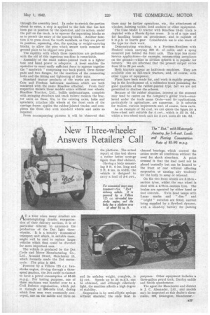
With regard to the pin-jointed rigid-girder track, this takes its name from the fact that it hinges only in the direction prescribed by the curvature of the wheels over which it runs. It will not bend the other way.. As a result, the reach from one wheel to the other acts, under the loads to which it is subjected in normal earvice, as a rigid plate, and this " plate," let it be noted, does not lie in a plane, but, in elevation, describes an arc.
This brings us back to the lifeboat
carriage. First condition to be fulfilled in this vehicle is that it shall be capable of running easily, when heavily laden, over soft sand or shingle, where rolling resistance (for a wheel) may be as high as 300 lb, per ton.
It is a fact that a rough working measure of rolling resistance is provided by the area of the cross-section (not the volume) of the rut made by the wheel. Clearly, then, widening the wheels does not solve the problem. A wide-rimmed wheel will not sink in so deeply, but the cross-sectional area of the rut will not be lessened. On the other hand, increasing the diameter of the wheel does achieve the clashed object.
However, there are obvious practical limits to the diameter to which a suitable wheel can be made. A 6-ft. wheel may be the largest that can conveniently be employed. However, the radius of the arc formed by the track of the Roadless three-wheel unit may be, say, 15 ft.; therefore, it is equivalent to a wheel of 30 ft. diameter; the rut is proportionally small in cross-section and the rolling resistance low, One may ask, why have an arc at all; why not a flat track? Steering is an important reason; the curved track, to some extent, can pivot on its central and lowest portion. In addition, there is a mechanical reason associated with the method by which the track locks itself. Reverting to the design of the track, considerable ingenuity has been exercised in affording the required rigidity without subjecting the pins of thejoints to any stress other than the very light loading required to hold the links together. Each link, or shoe, is provided with projecting fingers, two pointing forwards and two—off-set in respect of the others—pointing rearwards. The ends of both pairs lodge in notches in the adjoining shoes, bearing upwards on the tipper walls of the notches (considering the shoes in the lower run). As a result of this arrangement the entire load is taken by the fingers, no part in affording rigidity and resisting backward bending being played by the joint pins.
Any shoe functions like a pinch bar, the point being the fingers which fit into the notch of the next shoe, the fulcrum being where the notch rests on the fingers of the adjoining shoe, and the body of the shoe corresponding to the handle of the bar.
We asked Col. Johnson what was the output of these girder tracks. He replied that during the past three or four years. the works had been producing 250-350 .units per week for various purposes.
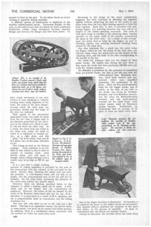
No difficulty is presented by the operation of assembling these pin-jointed tracks, but that is not the case with the rubber-jointed type. Machines, how ever, have been evolved and constructed which have expedited immensely the production of the latter. There are two power-operated tools for the bigger tracks, one of « which, at the time of our visit to the works, was set-up for FordsonRoadless and Case-Roadless tractors, and the other for Bristol-Roadiess tractors, and one hand-operated machine for the small tracks (with bolted joints) used on Ransomes garden tractors. Incidentally, we understand that an average of 15 pairs of these are made every week.
One of the bigger machines is illustrated. Its function is to constrain the parts, as the rubber blocks are introduced, into suitable relative positions for reception of the parts that follow, in the process of assembly. It must be remembered that the blocks are initially loaded.
Among its functions, the machine draws the track along through the assembly head. In order to stretch the portion about to enter, a stop is applied to the link that has last been put in position by the operative, and its action, under the pull on the track, is to squeeze the separating blocks so as to permit the entry of the spacing block. Another function is to press down the tooth members, as they are placed in position, squeezing, also, the spacing or weight-carrying blocks, to allow the pins which secure tooth member to ground plate to be slipped into place.
The rapidity with which these operations are performed with the aid of this ingenious machine is remarkable.
Assembly of the small rubber-jointed track is a lighter task and hand power is adequate. A lever enables the operative to exert easily sufficient force to squeeze together the " sandwich " comprising two back plates, three rubber pads and two flanges, for the insertion of the connecting bolts and the fitting and tightening of their nuts.
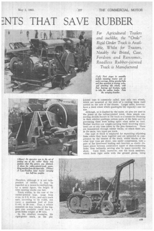
Standard tractor products of the works are converted Case and Fordson half-track machines which are both marketed with the name Roadless attached. From their respective makers these models arrive without rear wheels. Roadless Traction, Ltd., builds undercarriages, complete with swinging drawbars and track rollers; mounts the tractor units on these; fits, to the existing axles, hubs and sprockets; attaches idle wheels at the front ends of the carriage frame; applies the rubber-jointed tracks; and completes the front end with standard wheels and axles as required.
From accompanying pictures it will be observed that there may be further operations, viz., the attachment of winches, hoisting tackle, land anchors or other equipment.
The Case Model D tractor with Roadless 13-in: track is depicted with a Morris 2f-ton crane. It is of a type used for handling bombs on aerodromes, and is capable of 9 m.p.h. in fourth gear. Considerable use is also made of the type for dock work,
Demonstrating winching, is a Fordson-Roadless with Hesford winch carrying 300 ft. of cable, and a sprag mounted just behind the front axle. This type has many Service applications—for example, manceuvring aeroplanes on the ground—whilst in civilian spheres it is popular for forestry. We are informed that the present output varies from 10 to 20 per week.
Both tractors appear as half-track machines, They are available also as full-track tractors, and, of course, with other types of equipment.
Plans have been made for, and work is rapidly progressing in the development of, a rubberless track possessing the good qualities of the rubber-jointed type, but we are not permitted to disclose the scheme.
Because of the rubber situation, interest at the moment may tend to centre on the company's girder track—marketed under the trade name Orolo—and its applications, particularly in agriculture, are numerous. It is suitable for trailers, various implements and, of course, farm carts.
As an example of the cost, we can quote the figure for a three-wheel unit suitable for 4 cwt., which is £2 2s. 6d., whilst a two-wheel track unit for 2 cwt. costs £1 14s. 6d.