


A MISCELLANY OF INVENTIONS.
Page 32
If you've noticed an error in this article please click here to report it so we can fix it.
A Résumé of Recently Published Patents.
AN INTERESTING and ingenious device for facilitating the adjust. rnent of brakes is described and illustrated in specification No. 178,812, by Societe Anon. Aeroplanes Henri and Maurice Farman. There is a worm and sector connection between the brake cans operating spindle and the cam itself. A square on the end of the worm spindle allows of its being turned, and so, through the medium of the sector with which it is in engagement, altering the angular relation between:, the cam and
th.-owing the carr farther in tho direction of operatirT the brakes, and thus effecting the necessary adjustment.
"Improvements in and Relating to Lifting and Slewirg of Motor Vehicles and the Like" is the subject of Specification No. 179,183, in which a rnechanti cal device is described by Aldo Fiorentino. A substantial framing is attached to the chassis of the motor vehicle, about the middle of its length. Carried on the four arms of this framing are four cylinders, which serve as guides for plungers, which are provided with ratchet teeth. The latter Are in engage 'tient with spring-operated stops. The lower ends of the plungers carry a ring which bears upon the inner ends of three levers which, at their enter ends, are provided with feet. A hand lever located near to the driver's seat controls the movement of the plungers, and may be used to raise the levers, or lower them, so that they are either carried idly close up to the underside of the chassis, or are disposed with the feet resting on the ground. The spring stops which are in engagemen't with the ratchet teeth on the plungers are released, as iequired, by the operation of the usual typo of small lever, carried on the main hand lever, as in the case of an ordinary side brake lever. When the hand levet is moved into that position in which the feet come into contact with the ground, it operates a clutch, which sets in motion an engine-driven pump, which delivers fluid at high pressure to a large cylinder which is mounted in the main frame of this device, propelling a plunger within the cylinder, and causing further movement of the legs, so that the vehicle is raised from the ground. Other mechanism is provided, by means of which the chaaais may then be revolved or slewed into any new position, when the pressure in the main cylinder is released, and the vehicle deposited once more upon its own wheels.
C. Fulton connects a speedometer and a flownieter, so that it is possible to read, on the combined instrument, the speed at which a car is travelling, in miles per hour, the consumption of petrol in galdons per hour, and also the consumption of fuel in terms of miles per gallon. Several methods of attaining the end in view are deacribed and illustrated in the specification, No. 194,756.
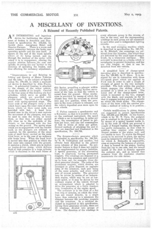
The dynamo-electric generator which Is patented in specification No. 194,764, by E. B. Collingham and another, has already been described in the general news columns of this journal. Its par. tieular feature is that it does not require to be supplemented by storage batteries. i. special generator, of the alternating tape, is employed, having permanent magnets. The windings are disposed on a single fixed ring armature and connected up to form, say, for example, three distinct generator circuits. The poles of the peimanent magnets, which revolve, are arranged in pairs disposed on opposite sides of the armature, each pair being of the same polarity, and every other pair of reverse polarity. The generator may be driven by means of an independent engine, which may be run at conatant speed, or it may lie driven by the ordinary engine of the vehicle through an arrangement which is adapted to drive the generator at a fairly constant rate, irrespective of the engine speed.
The armature is in the form of a flat iron ring or annulns, on which the windings. are wound directly, in a single layer, thus reducing to a minimum the distance between the revolving magnets and the armature. In a machine designed as suggested in this specification, having three generator circuits, there are 24 windings, divided into groups of three. The direction of the windings in every alternate group is the reverse of that in the next, and the corresponding windings in each group are all connected to each other and to independent lighting circuits.
In the road sweeping machine which is described in specification No. 194,779, Jay R. Mitchell, the sweepings are col. lected from the chamber, into which they are delivered by the usual type of rotary brush, by a transverse conveyor. The ecniveyair is mounted on a frame which is rectangular in general formation, and has one side hinged, so that it can be detached from the vehicle.
A simplified form of change-speed operating gear is described in specification No. 194,902, by F. Shaw. It is designed for use in connection with those two-speed gears which are applied to Ford cars in order to add a couple of changes of speed to the two normally provided. The fork within the gearbox. which engages the sliding wheel mounted on a block on a shaft. The lower end of the change-speed lever, which is mounted an the box, engages with the block, and projeets so far in that it engages notches cut in the spindle en which the block slides. The engagement of the lever with the notches provides a method of locking it in position.
Certain modifications in piston design are suggested in patent specifications " Nos. 194,936 and 194,959. In the former, which is by W. T. Cave, the gudgeon pin is retained in its place in the piston by means of a spring located inside it, on to the ends of which are screwed a couple of flanged bushes, the flanges being partly rectangular, so that when in position they register with similarly shaped recesses in the piston wall, and are unable to turn. To enable the flanged pieces to be screwed in place, the spring must be temporarily extended. The other, for which A. Renaudin is responsible, aims at improving the balance of pistons. A duct is formed in the piston, leading from the top to one side, and the lateral mouth of the duct is directly opposite the gudgeon pin, and so located that pressure from the explosion chamber counteracta the side thrust.