 1
1 2
2 3
3 4
4 5
5 6
6 7
7 8
8 9
9 10
10 11
11 12
12 13
13 14
14 15
15 16
16 17
17 18
18 19
19 20
20 21
21 22
22 23
23 24
24 25
25 26
26 27
27 28
28 29
29 30
30 31
31 32
32 33
33 34
34 35
35 36
36 37
37 38
38 39
39 40
40 41
41 42
42 43
43 44
44 45
45 46
46 47
47 48
48 49
49 50
50 51
51 52
52 53
53 54
54 55
55 56
56 57
57 58
58 59
59 60
60 61
61 62
62 63
63 64
64 65
65 66
66 67
67 68
68 69
69 70
70 71
71 72
72 73
73 74
74 75
75 76
76 77
77 78
78 79
79 80
80 81
81 82
82 83
83 84
84 85
85 86
86 87
87 88
88 89
89 90
90 91
91 92
92 93
93 94
94 95
95 96
96 97
97 98
98 99
99 100
100 101
101 102
102 103
103 104
104 105
105 106
106 107
107 108
108 109
109 110
110 111
111 112
112 113
113 114
114 115
115 116
116 117
117 118
118 119
119 120
120 121
121 122
122 123
123 124
124 125
125 126
126 127
127 128
128 129
129 130
130 131
131 132
132 133
133 134
134 135
135 136
136 I VECO Ford's new flagship is the 190.48 TurboStar tractive unit
Page 117
Page 118

Page 119
Page 120
If you've noticed an error in this article please click here to report it so we can fix it.
(or 230.48 if fitted with three axles). Its 350kW (476hp) engine is the charge-cooled version of the twinturbocharged 17.2-litre V8 engine used in the traditional 313kW (420hp) TurboStar.
Servicing this technology-laden beast is not the simplest of tasks, but if approached in a methodical manner is not too daunting. These vehicles have three levels of service designatd the Bl, B1+B2 and the Bl+B2+B3, with an additional inspection-only S-service. A chart shows which service is needed by providing cross-references to the annual distance covered with the actual odometer reading.
Vehicles travelling less than 30,000km a year should be serviced every 10,000km. Vehicles carrying out an average amount of work (30,000-90,000km a year) are serviced every 15,000km while those clocking more than 90,000km annually receive the treatment every 30,000km. Having decided on the frequencies of service, they are carried out in the normal A-BA-C sequence.
Workshop went along to Zenith Trucks in Reading to watch as a 190.48 was serviced by fitter John Curtis. Curtis has been with Zenith for 20 years and has attended many manufacturer run courses including the familiarisation one on the 190.48.
The vehicle has not clocked up many miles, but Curtis went through most of the procedures of the B1+B2+B3 service for our benefit. This would usually only happen every 12 months or 120,000 kilometres. In general he finds that many of the niggling complaints that drivers report are caused when they do not fully understand all the features of this very hi-tech vehicle. There were no such reports with our vehicle which, incidentally, was fitted with the Fuller 13-speed gearbox.
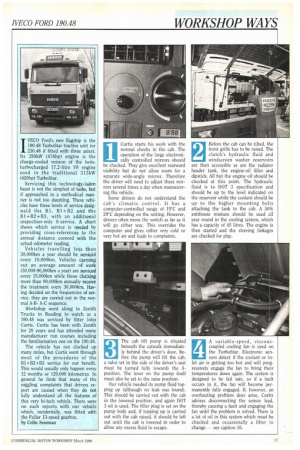
by Colin Sowman Curtis starts his work with the normal checks in the cab. The operation of the large electronically controlled mirrors should be checked. They give excellent rearward visibility but do not allow room for a separate wide-angle mirror. Therefore the driver will need to adjust these mirrors several times a day when manoeuvring the vehicle.
Some drivers do not understand the cab's climatic control. It has a computer-controlled range of 15°C and 29°C depending on the setting. However, drivers often move the switch as far as it will go either way. This overrides the computer and gives either very cold or very hot air and leads to complaints. Before the cab can be tilted, the front grille has to be raised. The clutch's hydraulic fluid and windscreen washer reservoirs are then accessible as are the radiator header tank, the engine-oil filler and dipstick. All but the engine oil should be checked at this point. The hydraulic fluid is to DOT 3 specification and should be up to the level indicated on the reservoir while the coolant should be up to the higher mounting bolts attaching the tank to the cab. A 50% antifreeze mixture should be used all year round in the cooling system, which has a capacity of 45 litres. The engine is then started and the steering linkages are checked for play.
3 The cab tilt pump is situated
beneath the catwalk immediate ly behind the driver's door. Be fore the pump will lift the cab, a valve set in the side of the driver's seat must be turned fully towards the Aposition. The lever on the pump itself must also be set to the raise position.
Our vehicle needed its pump fluid topping up (although no leak was found). This should be carried out with the cab in the lowered position, and again DOT 3 oil is used. The filler plug is set on the pump body and, if topping up is carried out with the cab raised, it should be left out until the cab is lowered in order to allow any excess fluid to escape. A variable-speed, viscouscoupled cooling fan is used on the TurboStar. Electronic sensors detect if the coolant or inlet air is getting too hot and will progressively engage the fan to bring their temperatures down again. The system is designed to be fail safe, so if a fault occurs in it, the fan will become permanently fully engaged. If, however, an overheating problem does arise. Curtis advises disconnecting the sensor lead, thereby causing a fault and engaging the fan until the problem is solved. There is a lot of oil in this system which must be checked and occasionally a filter to change — see caption 16.
The power-steering fluid reservoir is situated just behind the radiator. Its smaller cap has a dipstick fixed to it which is used to check the fluid level. Normally the fluid should be on the flattened portion of the dipstick. However, if for some reason the engine is running while the check is carried out, the required level is one to two centimetres above the top mark. At every major service (B1-EB2+B3) the filter in the reservoir should be changed. The system holds 4.6 litres of automatic transmission fluid type-A or Dextron II D. 6 While still at the front of the
engine, check the alternator and compressor belts (access to the compressor belt can be easier from underneath the vehicle). Having satisfied himself that the belts are in good order and tight enough, Curtis does a general check around on top of the engine for leaks or loose belts. Pay special attention to the inlet air trunking to and from the intercooler as the boost pressure of 1.5 bar (21psi) will blow off any pipe not securely fixed.
7 Two filters, a sediment bowl
and a water separator are used in the TurboStar's fuel system.
The filters are not changed at every service. Again, the identification sheet and service sheet need to be consulted to see if a filter change is required. In our case it was. Curtis uses a strap wrench to remove the two renewable cannister-type filters from their housing at the front offside of the engine. When fitting the new ones, ensure that the 0-ring seal is properly in place on the top of the filter and smear some grease onto it so that it does not pick up on the housing and jump out of the groove. This type of filter needs only hand tightening. With the new filters fitted into their housing, Curtis turns his attention to the sediment trap and water separator which are situated next to the cab tilt pump. A plastic over-centre type clamping arrangement is used to secure the glass sediment bowl. This clamp should be undone, the gauze filter blown out and the bowl emptied and cleaned before it is reassembled.
A thumb screw in the bottom of the water separator must be removed to let any water out — a couple of strokes of the priming pump will help. Returning to the fuel filters at the front of the engine, undo both bleed screws on the top of the housing. Operate the priming pump until neat fuel without any air bubbles comes out of the rearmost bleed screw, then close it. Continue pumping until all the air is removed from the front filter and close the other bleed screw. A couple more pumps will push any remaining air onto the pump, which will bleed itself automatically.
10 There is a filter in the
cooling water system situ ated at the front nearside of the engine which should be changed at each service. Besides removing any debris from the coolant it also adds a corrosion inhibitor to the system. However, antifreeze must be added separately. To get to the filter some of the sound encapsulation must be removed. Have the new filter to hand with its 0-ring greased because there is no tap in the system and coolant will leak out until the replacement is fitted. The header tank may need topping up again.
11
Most crankcase breathers now feed back into the air intake system. On the 1/8 fitted into the TurboStar, this recirculated air is filtered through a wire-wool-type element which must be cleaned at each major service. Its housing is to the rear of the nearside bank of cylinder heads. On the intercooled version the outlet pipe from the lefthand turbocharger has to be removed to gain access. The six screws holding the top can be undone and the filter removed. After cleaning with a degreasing agent, the filter is replaced. Ensure that the diaphragm in the top is not split, if it is, replace it. There are four valves to each cylinder making setting the tappets quite involved. Cylinders starts with number one, at front right, moving back along that bank to four. Five is front left with eight at the rear. When facing the valves the exhausts are on the right. With number one cylinder "rocking", all the valves on two, five and six can be checked, number four and eight exhaust and number three inlet valves can be set. First adjust the bridge piece which contacts the two valves directly (0.05mm is recommended); it should be the same on both valves. This is checked and adjusted as shown.
12 13 Now the clearance between
the rocker and the bridge piece can be set. On the inlet side this should be 0.2-0.25mm, while exhausts should be 0.4-0.45mm. These dimensions apply to a cold engine that has stood for several hours. Number six cylinder is now set "rocking" and the remaining valve and rocker clearances set. Both the rocker boxes and covers are sealed with reusable 0-rings. The injectors should be replaced and 49Nm of torque applied to each clamp. Spill pipes should be replaced before the injector is fully onto its seating because it is difficult to tighten the union afterwards.
14 Next, Curtis checks the oil
level in the gearbox and back axle. The Eaton 13 speed transmission has a level plug in the nearside rear of the casting. This plug, with a hexagonal socket in it, is tapered and does not use a sealing device. Drain periods are 60,000-90,000km, depending on annual milage, and 14 litres of SAE 80W/90 non-EP oil is required. (The ZF option takes 16 litres). The rear axle also has a tapered plug, this time with a male hexagonal head and set on the offiside of the pinion housing. Drain periods are as per the gearbox and 22 litres of SAE 85W/140 EP oil are required. While engine oil should be changed every 15,000km, the replaceable cannistertype filters are changed ev ery 30,000km. After draining the sump, the two filters are removed with a strap wrench. They are positioned close to the sump pan and it is not that easy to get the wrench on them. There are two 0rings on top of each cannister — grease them both and do the filter up hand tight. With new filters fitted, 30 litres of SAE15W/40 multigrade oil are needed to refill the sump, but don't forget to put the plug back first and check its copper sealing washer.
16 To the rear of the engine
oil filters is another one, this time for the fan's vis cous coupling fluid. Curtis indicated this filter, which should be changed once a year along with the fluid. In our case all that was necessary was to check the fluid level in the reservoir situated at the back of the engine between the two banks of cylinders. The fluid should be above the top of the sight glass fitted to the reservoir and Dexton II D or automatic transmission fluid type-A should be used.
17 Rockwell Stopmaster twin
wedge brakes are fitted to the TurboStar and they are self-adjusting by design. Using two wedges gives the effect of a twin-leading-shoe brake. Their actuators are smaller than normal (except the park brake) without the usual spring and diaphragms inside, so they give very little problem with air leaks. Small actuators help when checking the brake lining thickness by allowing more room behind the backplate. The normal windows are fitted to the top and bottom of the backplate allowing inspection of each shoe. There are wear limit ridges to indicate when a reline is necessary.
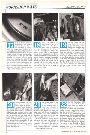
18 There is a filter in the
range-change air feed which should be cleaned every major or intermediate service. This sintered filter is to be found in a housing at the back of the gearbox, to the right of the propshaft with a large hexagonal top. Before attempting to remove the top, all the air must be depleted, otherwise the housing will have pressure inside. Once all the pressure has been lost the top can be removed and the filter taken out and cleaned by using an air line. The filter is then replaced and the top put back on — but not too tightly.
19 Now he knows that the
brake drums do not have to be removed, Curtis checkes the kingpins and wheel bearings. A bar inserted through the bottom of the raised front wheel will detect any play in the kingpin, while putting it through the top will highlight slack in the wheel bearing. All wheels are now lowered to the ground and the wheel nuts (all righthand thread) are torqued to 400-450Nm. It is important that this check should be carried out at each service including the inspection only one — and even more often than that if possible.
20 Having checked the king
pins, Curtis now raises the vehicle again to grease it.
There are grease nipples on the top and bottom of each kingpin and one on the front shackle of each spring (the fronts face outwards but the rears in). Another two nipples are to be found on the swinging shackles at the rear of each spring with a final two in the propshaft universal joints but not on its slider. Steering joints are sealed for life and can only be replaced if they are worn. The clutch-release bearing does not require greasing, either — nor the clutch itself need adjusting. The air drier, which is situated beneath the catwalk on the nearside, has a filter. This should be changed every 12 months so was not required on our service, but Curtis indicated where it is for our benefit. Some of these units have a small clampbolt on the chassis side of the housing, so check before trying to remove the filter.
The main engine air filter is changed only every two years but is blown out when the clog indicator light in the cab comes on. Curtis advises that when undoing the wire clips holding the filter cover it is necessary to use a screwdriver — the springs are very strong.
21
22 On this TurboStar, ABS
braking is fitted as stan dard. If any arc welding is necessary on the vehicle or bodywork, this must be disconnected. Taking the battery leads off will not protect the electronics. When four screws are undone at the bottom of the cab's centre console, the electronics will then slide out. The main multipin plug must be removed before any welding starts. Batteries should have their electrolyte level and terminal connections checked. The service is now finished. At Zenith the road test is always carried out by a different fitter to the one who did the work. All was satisfactory.