


A Novel Chassis Layout
Page 58
If you've noticed an error in this article please click here to report it so we can fix it.
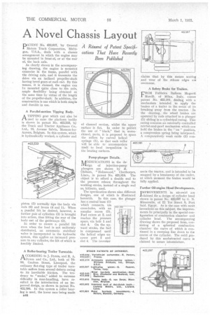
A Résumé of Patent Specifications That Have Recently Been Published PATENT No. 422,617, by General Motors Track Corporation, MiChigan, U.S.A., deals with a chassis arrangement in which the engine may be mounted in front of, or at the rear of, the back axle.
As clearly shown in the accompanying drawing, the engine is mounted crosswise in the frame, parallel with the driving axle, and it transmits the drive via an inclined propeller-shaft having bevel gears at each end. By this means, it is claimed, the engine can he mounted quite close to the axle, ample flexibility being obtained at the same time by virtue of the length of the propeller-shaft. In addition, the construction is one which is both simple and durable in use.
A Parallel-motion Tipping Body.
ATIPPING gear which call also be used to raise the platform bodily is shown in patent No. 422,533, by the Truck and Tractor Appliance Co., Ltd., 18, Avenue Salvia, Merxern-lezAnvers, Belgium. In this system, which is hydraulically worked, a cylinder and
piston (5) normally tips the body via rods (6) and levers (4 and 1). When a, parallel lift be desired, however, a further pair of cylinders (3) is brought into action, thus lifting the rear of the body out of the guideways (2).
In order to ensure a parallel lift even when the load is not uniformly distributed, an automatic stabilizer valve is incorporated in the hydraulic system, this applies an increased pressure to any cylinder, the lift of which is forcibly limited.
A Roller-bearing Trailer Turntable.
ACCORDING to J. Dyson, and R. A. Dyson and Co., Ltd., both of 7680, Grafton Street, Liverpool, the ordinary fiat-ring type of trailer turntable suffers from several defects owing to its inevitable friction. The tendency to "snake," added to extreme difficulty in man-handling, have resulted in the introduction of an improved design, as shown in patent No. 422,390. In this system a roller bearing is used, the lower race being made
IA4 Pump-plunger Details.
fiODIFICATIONS in the doalsign of injection-pump plungers are shown by R. Oldham, " Holmwood," Cleethorpes, Lincs., in patent No. 421,818. The object is to afford a double seal to the pressure release throughout the working stroke, instead of a single seal as, hitherto, used.
The specification shows nine different designs, one of which is illustrated herewith. In this case, the plunger has a central bore (1) which connects, via cross-holes, with an annular recess (3). Fuel enters at 2, and reaches the pressure space, via hole 1 and slot 4. On the upward stroke, the fuel is compressed until the helical edges uncover port 2 and slot 4. The inventor claims that by this means scoring and wear of the release edges are overcome.
A Safety Brake for Trailers.
FROM Fabbrica Italiana Magneti Marelli, of Milan, Italy, comes patent No. 422,381, dealing with a mechanism intended to apply the brakes of a trailer in the event of its breaking away from the tractor. In the drawing, the wheel brakes are operated by rods attached to a plunger (1) sliding in a cylindrical casing. This casing contains an externally controlled ratchet-and-pawl mechanism which can hold the brakes in the " on" position, a compression spring being interposed. A comparatively weak cable (2) con
nects the tractor, and is intended to be snapped by a breakaway of the trailer, at which moment the brakes would be fully applied.
Further Oil-engine Head Developments.
I'IMPROVEMENTS in air-swirl are claimed for a design of cylinder head shown in patent No. 422,097 by G. N. Minacoulis, of El Tor Street 8, Port Said, Egypt. As is the case with mot inventions on this subject, the improvements lie principally in the special configuration of combustion chamber and cylinder head. The accompanying drawing shows the proposed form, consisting of a spherical combustion chamber the curve of which is continued in a sweeping line down to the centre of the cylinder. The swirl produced by this unobstructed curve is claimed to assure intermixture.