


A Simple Form of Servo Brake
Page 68
If you've noticed an error in this article please click here to report it so we can fix it.
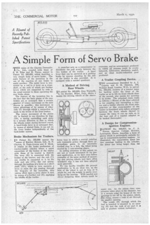
THE name of the Clayton Dewandre Co.' Ltd., coupled with those of S. E. Edge and M. Payne, appear in Patent No. 365,655, which describes a very simple form of servo brake. The main feature of the invention is the use of the reaction of one brake to apply another. The pedal lever is connected by a rod to a lever on a crossshaft, at the ends of which are further levers which are connected by rods in the usual manner to those operating the rear brake shoes.
The feature of the invention lies in the fact that the back plates of the rear brakes are so arranged that a certain amount of rotary movement on the axle sleeves is possible ; this movement is taken advantage of by means of other rods (7) through which a connection is made to the levers of the front brakes.
The rotary movement of the plates (5) is limited in one direction by dogs (10), a spring controlling each plate in a reverse direction to that in which the wheels rotate during forward travel. A hand-brake lever is so arranged that, by means of slotted links, it can act on the front brakes independently of the back-brake system.
Brake Mechanism for Trailers.
IN Patent No. 365,668 appear the
names of Karrier Motors, Ltd., R. P. Clayton, R. Dean-Averns and P. Meek. It relates to the brake mechanism of tractor-trailer vehicles where a quick connection of the brakes of the trailer with those of its tractor is desired. The lever (B) is connected with the brakes of the tractor, and the rod (V) can readily be connected to it by the fork and pin (V1), the rod acting through the medium of a lever on a short shaft (111), which in turn operates a lever to raise the pin passing through the king-pin of the turntable, thus taking effect upon a, lever above it and, by means of a further rod (N), applying the brakes of the trailer.
A cross-bar acts as a compensator to distribute the pull evenly between the two brakes of the trailer. A hand lever that can he operated as a parking brake by anyone standing by the side of the trailer is also provided. It is equipped with a ratchet quadrant.
A Method of Driving Rear Wheels.
IN patent No. 363,922, Gino Turinelli, 2, via Berchet, Milan, Italy, shows a means for driving wheels of the sleeve borne type in which a central rotating axle transmits power thropgh three intermediate gears to an internally toothed ring in a hub, the wheel being carried by a non-rotating sleeve.
In calling attention to this patent we are not so much interested in its present application, as we have seen before examples of the same method of mounting and driving wheels and have often wondered why it has not been adopted more generally.
We can hardly consider the present application to be an ideal one, as the boss of the wheel is not so long as it might be, and the weight is partly. overhung on the bearing. With careful and clever designing these defects could be
overcome, and an arrangement produced in which all stresses could be evenly balanced, lubrication absolutely sealed, and an ideal double-reduction gear produced.
A Trailer Coupling Device.
THE arrangement described by A. I.
Logette and E H. Dainton, 186, Weimer Road, London, W.11, in patent No. 356,232, consists of a tractor ramp for backing under the front of the trailer so as to lift its front wheels clear of the ground, also means for securing it by hooks. The principal claim reads as follows :—Means of the kind referred to for coupling and uncoupling a tractor and a trailer wherein the front axle, axle-tree or like cross-member of the trailer is furnished with rollers arranged between the front wheels thereof to engage the ramp or run up rails on to the rear end of a tractor adapted to be backed thereunder.
A Design for Compressionignition Engines.
PATENT No. 365,617, by C. A. Breeze, Agarton Cottage, Everton, Lymington, Hants, describes a form of piston which is particularly suitable for use in compression-ignition engines. As illustrated, the compression space has two openings leading to the cylinder, the lower one being larger than the upper one. As the piston rises, compression takes place in the chamber, but at a certain point the larger of the two openings is cut off by the piston, which, gfill rising, causes a rush of air through the smaller opening.
The nozzle (9) through which the fuel is injected is situated in an opening (6) and the rush of air past it is said to produce violent turbulence.