


MOTOR ROAD SWEEPERS.
Page 32
If you've noticed an error in this article please click here to report it so we can fix it.
A Resume of Recently Published Patents.
Clayton and Co., Ltd., draw attention, under specification No. 156924, to a minor difficulty which arises in connection with the design of motor road sweepers, and particularly in regard to the type which they' manufacture, viz., that in which a collector for the road sweepings is embodied with the sweeper as one self-contained machine. The problem is this: Owing to construetonal difficulties, it is not possible to make the brushes and the collecting
casings as wide, overall, as the machine itself. The outer extremities of the casing must conic inside the rear wheels of the vehicle. A machine so constructed, and without any special provision to obviate the trouble named, would be inefficient, inasmuch as there' would always • remain a portion of the road nnswept, viz., that extending from the edge of the sweeper to the outside of the road wheels; moreover—and this is particularly important to note—the unswept portion avould be the gutter, or the part of the roadway nearest: the kerb where, as a matter of fact, most of the refuse . tends to gravitate and accumulate.
An improved construction, as described in the specification named, is designed to obviate this particular difficulty. It consists, briefly described, of auxiliary brushes, carried in front of the main brushes, disposed obliquely to the line of travel of the vehicle, and extending so far to one side that it is possible to sweep the roadway right out to the kerb without the road wheels coming in contact therewith. Moreover, as a result mainly of the diagonal position of the auxilia7 brushes, the refuse which they collect is directed inwardly towards the middle of the vehicle, where it is subsequently collected by the main brushes and delivered into the repository which
1328 the vehicle carries for refuse. An incidental advantage of this arrangement is that the sweepings -which, in the ordinary way would tend to be thrown off at the ends of the main brushes and thus be left in the roadway, are pushed towards the middle of the vehicle by the auxiliary brushes, and• the result is that there is actually nothing near the end of the main brushes for them to collect, and, therefore, the unfortunate tendency named is obviated. .
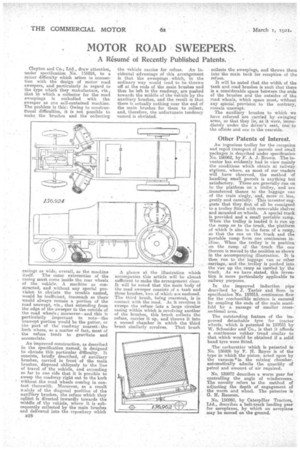
A glance at the illustration wl ich accompanies this article will -be almost sufficient to make the arrangement clear. It will be noted that the main body of the road sweeper consists of a tank and three brushes, two of which are enclosed. The third brush, being rearmost, is in contact with the road. As it revolves it sweeps the refuse into a large circular casing within which is revolving another of the brushes, this brush collects the refuse, carries it up, and throws it into a second chamber in which the third brush similarly revolves. That brush
collects the sweepings, and throws them into themain tank for reception of the refuse.
It will be noted that the width of the tank and road brushes is such that there is a considerable space between the ends of the brushes and the outsides of the road wheels, which space must, without any special provision to the contrary, remain unswapt. The auxiliary brushes to which we have referred are carried by swinging arms, so that they lie, as it were, immediately tinder the driver's seat, one to the offside and one to the nearside.
Other Patents of Interest.
An ingenious trolley for the reception and rapid transport of parcels and small packages is described under specification No. 156962, by F. A. J. Brown. The inventor has evidently had in view mainly the conditions which obtain at railway, stations, where, as most of our readers will have observed, the method •of handling small parcels is anything hut satisfactory. These are geneaally run on to the platform an a trolley, and are _transferred thence to the luggage van of the train singly, and, more or less, gently and carefully. This inventor suggests that they first of all be consigned to a trolley fitted with removable shelves and mounted on wheels. A special truck is provided and a small portable ramp. When the trolley is loaded it is run up the ramp on to the truck, the platform of which is also in the form of a ramp, so that the one on the truck and the portable ramp form one continuous incline. When the trolley is in position • On the ramp of the ' truck the one thereon is moved to the position as shown in the accompanying illustration. It is then run to the luggage van or other carriage, and the, trolley is pushed into the van up the ramp as carried by the truck. As we have stated, this invention is more particularly applicable to railway purposes.
In the improved induction pipe described by J. Taylor and Sons in specification No. 157015, continuous flow for the combustible mixture is ensured by coupling the ends of the main manifold by a passage of smaller cross-' sectional area.
The outstanding feature of the improved detachable tyre for tractor wheels, which is patented in 157031 by W. Schneider and Co., is that it affords a continuous rubber tread similar to that. which would be obtained if a solid band tyre were fitted.
The carburetter which is patented in No. 156926 by F. II. Royce is of the type in which the piston, acted upon by the vacuumll'in the mixing chamber, automatically admits the quantity of petrol and amount of air required.
No. 159972 describes a worm gear for controlling the angle of windscreens. The novelty refers to the method of adjusting the depth of engagement of the worm and wheel. The patentee is G. H. Ransom.
No. 156960, by Caterpillar Tractors, Ltd., describes a belt-track landing gear for aeroplanes, by which an aeroplane
may be moved on the ground.