 1
1 2
2 3
3 4
4 5
5 6
6 7
7 8
8 9
9 10
10 11
11 12
12 13
13 14
14 15
15 16
16 17
17 18
18 19
19 20
20 21
21 22
22 23
23 24
24 25
25 26
26 27
27 28
28 29
29 30
30 31
31 32
32 33
33 34
34 35
35 36
36 37
37 38
38 39
39 40
40 41
41 42
42 43
43 44
44 45
45 46
46 47
47 48
48 49
49 50
50 51
51 52
52 53
53 54
54 55
55 56
56 57
57 58
58 59
59 60
60 61
61 62
62 63
63 64
64 65
65 66
66 67
67 68
68 69
69 70
70 71
71 72
72 73
73 74
74 75
75 76
76 77
77 78
78 79
79 80
80 81
81 82
82 83
83 84
84 85
85 86
86 87
87 88
88 89
89 90
90 91
91 92
92 93
93 94
94 95
95 96
96 97
97 98
98 99
99 100
100 101
101 102
102 103
103 104
104 105
105 106
106 107
107 108
108 109
109 110
110 111
111 112
112 113
113 114
114 115
115 116
116 117
117 118
118 119
119 120
120 121
121 122
122 123
123 124
124 125
125 126
126 127
127 128
128 129
129 130
130 131
131 132
132 133
133 134
134 135
135 136
136 137
137 138
138 139
139 140
140 141
141 142
142 143
143 144
144 145
145 146
146 147
147 148
148 149
149 150
150 151
151 152
152 153
153 154
154 155
155 156
156 157
157 158
158 159
159 160
160 161
161 162
162 163
163 164
164 165
165 166
166 167
167 168
168 169
169 170
170 171
171 172
172 173
173 174
174 175
175 176
176 177
177 178
178 179
179 180
180 181
181 182
182 183
183 184
184 185
185 186
186 187
187 188
188 189
189 190
190 191
191 192
192 193
193 194
194 195
195 196
196 197
197 198
198 199
199 200
200 201
201 202
202 203
203 204
204 205
205 206
206 207
207 208
208 209
209 210
210 211
211 212
212 213
213 214
214 215
215 216
216 217
217 218
218 219
219 220
220 221
221 222
222 223
223 224
224 225
225 226
226 227
227 228
228 229
229 230
230 231
231 232
232 233
233 234
234 235
235 236
236 237
237 238
238 239
239 240
240 241
241 242
242 243
243 244
244 245
245 246
246 247
247 248
248 249
249 250
250 251
251 252
252 The Control of Exhaust Braes
Page 141
If you've noticed an error in this article please click here to report it so we can fix it.
THROTTLING the exhaust is coming I. more into use for braking vehicles, but it is important thlt the throttling should not be carried far enough to cause the engine to stall. A control mechanism for rendering this impossible is shown in patent No. 744,513 (Clayton Dewandre Co., Ltd., Titanic Works, Lincoln).
The exhaust pipe (1), upstream of the silencer, is fitted with a butterfly valve for throttling purposes. It is worked by rocking an external arm (2). A solenoid (3), when energized, can pull the arm into the throttling position against the force of a spring (4).
This spring is made to have an increasing rate; one way of doing it is to use two springs of differing lengths as shown. This is done because the resistance to movement is greatest when the throttle is shut. This can be offset, however, by using an off-centre butterfly valve.
Energization of the solenoid by closing a switch (5) applies the brake; the switch can be worked by the usual brake-pedal before the wheel-brakes come into action. Stalling of the engine can be prevented by the use of a centrifugal switch, or by taking the operating current from the dynamo side of the cut-out. A pressure-sensitive switch is also mentioned.
EXTRICATING A BOGGED VEHICLE
PATENT No. 746,636, shows a simple device for enabling a vehicle to raise itself when bogged. The patent comes from R. Omant, R. Grant and A. Martin, 1 lc Castlereagh Street, Sydney, Australia.
A tubular "spoke" (1) is provided with brackets (2) fitted with screws for jamming it outwardly into the wheel rim. Inside the tube is an adjustable screwed rod fitted with a swivel foot (3) on its end. The unit is attached to a bogged wheel as shown at 4, and when power is applied it should lift the wheel far enough to enable packing to be placed under it.
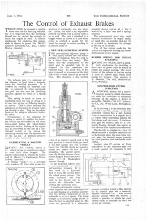
A NEW FUEL-INJECTION SYSTEM
THE conventional injection pump is very lightly loaded until the actual moment of injection; then, the load is, for a short time, very heavy. This means that the construction of the pump and its camshaft has to be designed for this maximum but transient load. To avoid this, it has been proposed to pre-compress the fuel and to use a timed injector as an on-off valve. The objection to this method
is that it an injector should stick in the open position it would discharge much of the fuel supply into one cylinder. Patent No. 746,280, shows an injection system that makes the best of both principles. The patent comes from the British Internal Combustion Engine Research Association, 111-112 Buckingham Avenue, Slough.
In the proposed scheme, fuel is pre-compressed to about half-injection pressure. It is then used as a hydraulic fluid to work the normal helically edged pump plunger. The pump camshaft has little work to do, having only to operate the slide-valve controlling the hydraulic fluid.
A small continuously running pump supplies the pre-compressed fuel to an inlet leading to a pressure accumulator (1), having compressed air on its underside to act as a spring. The pump plunger (2) is lifted by a large piston (3) when the fuel is admitted under it. The events are governed by a slide-valve
assembly shown end-on at 4; this is worked by a light cam and is springreturned.
The arrangement gives very rapid injection irrespective of engine speed; so rapid that an annular dash-pot (5) is provided to decelerate the plunger at the top of its stroke.
Two of the claims made for the system are improved starting and better performance at low speeds.
RUBBER SPRING FOR ENGINE STARTING
PATENT No. 748,078, shows a clockwork mechanism for providing a short burst of power such as would be needed for engine starting. The novel feature of the scheme is that the spring is made of rubber discs which store energy by torsion. The patentee is A. Moulton, The Hall, Bradford-onAvon, Wiltshire.
CONTROLLING PETROL INJECTION A CONTROL system for a petrol injection pump in which allowances are made for variations in volumetric efficiency of the engine, is shown in patent No. 744,806. (The S.U. Carburetter Co., Ltd., Wood Lane, Birmingham, 24.) In the drawing I is the induction pipe and 2 the injection pump. A throttle controlled venturi has a pipe leading from its constriction to a capsule stack (3) which, when expanding, reduces the fuel charge and vice versa. A continuation pipe (4) ensures that air is constantly flowing through this system so that there is little temperature difference.
The throttle is coupled to a cam (5) which controls a variable restriction (6) in the branch pipe; this cam takes control when the throttle moves towards its closed position and isolates the main venturi.
Another pipe (7) carries air from atmosphere to the induction pipe and a small venturi (8) translates it into pressure variation which is then applied to the control pipe via a manually adjusted restrictor (9). This branch, assumes control when the throttle is closed, a position in which the main venturi tends to diminish its effect due to low air velocity.