


Gas Turbines for Road Vehicles
Page 64
If you've noticed an error in this article please click here to report it so we can fix it.
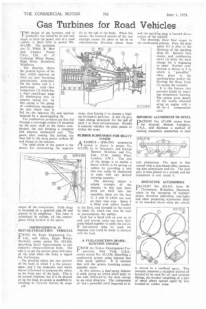
'THE design of gas turbines, and in particular, one suited by its size and shape to form the power unit of .a road vehicle, is dealt 'with in patent No. 01,589. The patentees ,arc G'. White, R. Barr and Centrax Power 'Units, Ltd., all of Catherine Wheel House, -.High, Street, Brentford, Middlesex.
The drawing shows the general layout of the unit, which operates on what are now becoming conventional princ:ples. On the intake end' is a multi-stage axial flow compressor (I) which has a final centrifugal stage (2) discharging into an annular casing (3). In .this casing is the group of combustion chambers '(it) into which fuel is fed via the injectors (5), and ignition initiated by a sparking-plug (6).
The combustion products are first led through a two-stage turbine (7) mounted on the same shaft as the intake compressor, the pair forming a complete and separate mechanical unit. The gases, after passing this turbine, are then fed to the main power turbine (8) and thence to the exhaust.
The chief claim in the patent is the means for constructing , the separate stages of the compressor. Each stage is mounted on a spigoted ring (9) and pinned to its neighbour. The rotor is cylindrical in outline, all the convergence being formed in the stator.
IMPROVEMENTS L's1 REFUSE-COLLECTION VEHICLES
FROM the Eagle Engineering Co., 11Ltd., and others, Eagle Works, WaniJick, comes patent No. 651,636, describing detail improvements in this concern's refuse-collection body. The aim is to get the presser plate well clear of the load when the body is tipped for discharging.
The drawing shows the rear portion of the body in which I is the presser,plate, and 2 the hydraulic ram which moves it forward to compress the refuse in the front part of the body, This is .itS normal function, but if it be desired „try. tip the load, jts action, is modified by arresting its forward motion by stops
.538 (3) on the side of the body. When this occurs, the forward motion of the ram carriage causes the plate to tip in an anti-clockwise direction about these
stops, thus forcing it to assume a highup horiiomal position.. A slot (4).provides••sliding movement for the end of strut 5 in these Circumstances. Handle 6 controls whether the plate passes or strikes the stops.
RUBBER SUSPENSION FOR HEAVY LOADS
A RUBBER SPRUNG suspension
system is shown in patent No. 651,578, by N. Straussler, and George Spencer Moulton and Co., Ltd., 13-14, Ashley Place, London, S.W.1. The aim of the design is to enable a heavy vehicle to be sprung on rubber by providing a unit that 'can easily be duplicated to cope with any desired carrying capacity.
The .drawing showsa simple example of the scheme; in this, case three units are built into one assembly; these are the bars (I, 2 and 3) which can rock on their own axes. Space 4 is filled with rubber bonded o the bars, and clamped to the frame by bolts (5), which can also be used to pre-compress the rubber.
Each bar is fitted with an arm on its end, and several units can have their arms linked together to unify the action. If lost-motion links be used, the response rate could be made to increase with the load.
A FUEL-INJECTION SPARKIGNITION ENGINE
FROM the Texaco Development CorI poration, New York, U.S.A.. comes patent No. 651,526, describing a combustion system using injected fuel with spark ignition. It is claimed that with the system, knocking cannot possibly occur.
In this scheme, a dual-spray injector is used, giving an initial small spurt to one side, followed by the main charge in an axial direction. The compressed air has a powerful swirl imparted to it, and the sparkrUg plug is located downstream of the injector.
The drawings • show four Stages in the combustion process. First, the pilot spray (I) is shot in the'. direction of the sparking plug (7). Ignition then occurs and combustion starts (3) while the main charge (4) is beginning to enter. Further combustion is shown at 5 in which a '` gun-effect" takes place in the sparking-plug pocket (6), blowing the flame front (7) across the cylinder.
It is this feature that prevents knock by ensuring progressive burning. The patent gives details of test results obtained using an engine with a 10to I compression ratio BONDING ALUMINIUM TO STEEL
PATENT No. 651,996 comes from 1 the General Motors Company, U.S_A., and discloses a method of making composite assemblies in steel
and aluminium. The steel is first coated with a zinc-based alloy, containing also aluminium and tin. The steel part is then placed in a mould, and the aluminium is cast round it.
MOUNTING ACCESSORIES
PATENT No. 651,135, from W. Christensen, Holstebro, Denmark, refers to the mounting of numberplates, direction indicators, rear-lights and other projecting accessories likely to be knocked about when the vehicle
is moved in a confined space. This inventor proposes a standard pattern of bracket to be used for all such exterior fittings, the bracket consisting of a pair of metal plates spaced apart by two bonded-on rubber arms.