


Electrically Operated Valves and Injection Pumps
Page 36
If you've noticed an error in this article please click here to report it so we can fix it.
PATENT No, 568,216 comes from A. CasteIlini and Robey and Co., Ltd., Globe Works, Lincoln, and shows a scheme for the electric operation of engine valves, and a like arrangement for working injection pumps.
An accompanying drawing shows the operating mechanism of the valves; to. the end of the stem is attached a laminated iron armature (1), which can be attracted into either the open or closed position by one of two solenoid coils (2), which are fitted with tubular cores. No return springs are employed, the closed position being electrically maintained. The current is supplied from the generator on the vehicle and the timing is performed by a rotary switch conveniently located.
The injection pump, shown in another drawing, consists of the usual plunger mechanism operating on wellknown principles. Instead of a camshaft, however, the plunger is moved magnetically. To its stem is attached a number of armatures (3), which collaborate with wound • cores (4) and so move the plunger. The long movement, always a problem with magnetic apparatus, is ingeniously obtained by arranging the cores in, what might be termed, a vernier relationship. A sliding switch (5) automatically energizes the next core ahead of the armature, so that continued motion is maintained. The timing is performed by the same rotary switch as .is used for the valves: and can be easily advanced or retarded by a simple system of movable contacts.
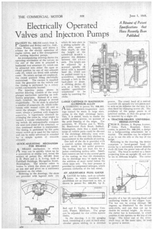
QUICK-ADJUSTING MECHANISM FOR BRAKES
ABRAKE mechanism, in which wear can be quickly taken, up by a screwdriver or similar tool, forms the subject of patent No. 567,991 from j. H. Pratt and J. S. Irving, both of Guildhall Buildings, Navigation Street, Birmingham. The scheme refers to brakes in which the shoes are opened at one end and pivot on a stationary abutment on the other.
Referring to the drawings, the shoes are provided with tapered ends (1)
which fit into slots in a sliding cylinder (2). The slots per in their depth, so that the height of the cylindrical m e rn b r governs the distance between the shoe ends The height can be adjusted by a screwed spindle (9) fitted with a serrated head (4), which can be pushed round by a screwdriver inserted through a tuffs in the back-plate or drum. A clicking_ device (5) acts as a leek, and enables quantitative adjustment to be made by counting the
LARGE CASTINGS IN MAGNESIUMALUMINIUM ALLOY
AGCORDING to patent No. 568,303, thin aluminium-magnesium castings cannot be made in large sizes, owing to the high shrinkage factor, This, it is stated, tends to render the middle portion porous, Cu account of the prior freezing of the edges. The patentees, W. Proctor and G. Webb, 53, Beechwood Park Road, Solihull, Birmingham, state that a much wider range of vehicle parts could be die-cast if the shrinkage difficulty were overcome, and to this end they disclose rn improvement in the methods of casting.
One half of the die is provided with a conduit system through which the molten metal is fed under'.pressure. The feeding lines are kept hot by a jacket containing molten salts. Smallbore runners are led to the central parts of the casting, so that the diminution due to shrinkage may be made up by the addition of more metal 'before the whole mass sets. The final pressure is provided by compressed nitrogen, which prevents oxidation of the hot metal.
AN ADJUSTABLE PLUG GAUGE
AGAUGE for holes, such as cylinder bores; in which roundness and parallelism are as important as size, is shown in patent No. 568,301, by E.
Ball and F. Taylor, 8, Murray Crescent, Pinner, MiddleSex. The gauge can he adjusted for size within narrow limits.
In the drawing, 1 is the gauging head, consisting of a pair of hard semicircular pieces sliding. in a dovetail groove. The coned head of a central drawbolt (2) spreads the two pieces and so acts as an adjuster for the size; it is then fixed by clamping screws (3). The periphery of the gauge pieces is of spherical outline, so that -the gauge can be inserted by a slight tilt.
A TRACTOR-DRAWN UNIVERSAL HEDGE-CUTTER CROM R. Holden, 5, Repton Avenue,
Gidea Park, Romford, Essex. comes, in patent No. 568,210, a design for a hedge-cutting attachment for a tractor. The machine can be adjusted so as to cut the side or the top of ti.e hedge.
Referring to the drawing, the device comprises a bevel-geared head (1) driven by a universally jointed slidable shaft (2) from the power take-off of the tractor. The head is carried on a beam projecting from an upright (3) and can be set to different heights. The cutter
oonsists of a bar (4) carrying fixed and oscillating blades of the clipper type. The bar can be swung through 180 degrees, as illustrated by the dotted semi-circle, and can thus cut up to double its vertical height. As shown, the chtter bar is horizontal, in which position it can operate on -the top of the hedge. The lower end of the drive. shaft may, at the same time, be used to power a mower.