


Single-plunger Injector for
Page 40
If you've noticed an error in this article please click here to report it so we can fix it.
Multi-cylindered Engine AN injection pump, claimed to be simpler and cheaper to produce than the usual type, forms the subject of patent No. 519,645 from Handels Aktiebolaget Vidar, Stock
holm, Sweden. The chief novelty is the use of a single compressing unit, in conjunction with a distributor for use with a multi-cylinder engine.
The drawing shows a pump suitable for a four-cylindered.engine. Only one plunger is used, the stroke of which is four times the normal. The cam (3) is of unusual form, comprising four lobes of increasing lift followed by a return drop. The plunger is thus moved in a series of four distinct steps, each step providing injection for one cylinder.
Distributing means comprise four discharge chaianers. (1) located at different heights in the cylinder bore, and the rising plunger charges each one in turn as the groove (2) comes in line. Four supply-and-spill channels (4) are used, whilst regulation is performed in the usual manner by rotation of the plunger. The foregoing is only an outline of the basic principle; three other patents cover the full details, the numbers being 519,646, 519,825, and 519,826.
P.S.V. OPERATOR'S SUPERCHARGED OILER DESIGN A MEANS for driving a supercharger IA for increasing the full-load output of an oil engine forms the subject of patent No. 519,513, which comes from G. Craven, of Halifax Corporation
Passenger Transport, Skircoat Road, Halifax. The. supercharger is driven from the shaft connecting the engine with the gearbox, so that its output varies with the speed of the engine.
In the drawing is shown the layout of the complete vehicle, in which the blower (3), driven by a belt (2) draws air through a silencer (4) and delivers it to the intake pipe of the engine. As the output of the blower may be inadequate at idling speeds there is a spring-loaded atmospheric valve (1) to ensure a supply at or about atmospheric pressure. As soon as the compressed air reaches this' valve, the valve (1) closes .and, from then on, the engine is pressure charged. The transmission system employed is that using an hydraulic clutch and a preselective gearbox.
METAL CUP-WASHERS FOR HYDRAULIC BRAKES
Pro increase durability, and to permit 1 the use of high pressures, are t'e objects of a design of hydraulic-brake cup-washer shown in patent No.
discs (1) clamped together on a screwed boss on the piston. Phosphorbronze and tempered steel are two suggested materials. An alternative method is to use, instead of the group of discs, a continuous helical strip, the
conical outline, however, .being retained. Another drawing shows the cup washer sealing on both the outer edge and the inner bore,
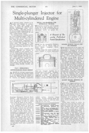
RINGED SLEEVE VALVE FOR' OIL ENGINES
THE heat-expansion of the upper end of a sleeve valve is of assistance in maintaining a working fit, but this, being absent when starting, has led to difficulty in reaching the high compression necessary for oil-engine selfignition. To overcome this trouble is the object of a design shown in patent No. 519,659 by A. Rowledge,
Ellerslie," Trowels Lane, Derby.
The drawing shows the upper end of a two-stroke oil-engine cylinder, in which the improved sleeve is thickened about the rim (4) for the reception of piston rings. These maintain the high compression when the engine is cold. Also shown are the combustion arrangements, consisting of a hot-plate (2) and the chamber (1) into which the fuel is injected. The exhaust valves (3) are controlled by the sleeve movement, the air inlets being presumably at the bottom of the stroke.
SLIGHT BRAKE BINDING BY DESIGN
ONE of the biggest problems in the design of brakes is to take up the slack before the actual application of the pressure; this slack is a widely variable quantity and has given rise to many types of self-adjusting
anism. A scheme shown in patent No. 519,787, by the Rover Co., Ltd., and P. Scott-Iversen, both of New Meteor Works, Coventry, is bold in its intentions. It is proposed to abolish slack altogether and to run with the shoes always pressing lightly on the drums.
Whilst there would, of course, he slight extra wear and loss of power, the patentees claim that these are negligible compared with the great advantages of the scheme. For example, with hydraulic brakes there would be practically no piston movement, so that leak-proof diaphragms could be used instead of the normal sliding pistons, with complex sealing devices.
Temperature-correction troubles, they assert, would vanish, and at all times the slightest pedal pressure would be instantly converted into braking effort. Moreover, there would be no need for any adjustment throughout the whole life of the linings.