


Transport Notes for
Page 26
If you've noticed an error in this article please click here to report it so we can fix it.
Those Who Run Bedfords NOW that new tyres, like new motor vehicles, are becoming more and more difficult to obtain—and more expensive—it is well worth while to spend a few minutes now and again checking up the points which affect tyre wear. One of the most frequent causes of excessive wear (other than hard driving) is play in the front hubs and this can be checked as follows:— Jack up the near-side front wheel, hold it at top and bottom and attempt to rock the wheel to and fro. If there be undue slackness, take off the hub cap, remove the splitpin from the castellated nut underneath, and tighten up the nut. When it is tight up, slacken back two castellations and replace the splitpin. Then repeat the same procedure on the other three wheels if you be working on a 30-40-cwt. model. On the 2-3-ton, 3-4-ton and 5-ton models the same instructions apply for adjustment of the front hvbs. The rear hubs have two nuts instead of .one, with a locking washer to hold them in position. The inner nut should be tightened up and slackened back two castellations, as described for the front hubs. Two tabs of the locking washer should be turned over to secure this nut in position, and the locking nut should be screwed on as tightly as possible, being retained by the other two tabs of the locking washer.
Obviating Play in Steering
To check play in the steering joints, jack up one of the front wheels, get someone to hold the steering wheel and grasp the road wheel at both sides. By pushing and pulling, you will be able to feel any play that exists in the joints. This play is usually due to normal wear over a long mileage, in the steering joints themselves or on the king-pins or their bushes. In any case, new parts may be needed to remedy the trouble, so the wisest plan is to run the vehicle into the nearest Bedford dealer and obtain his advice on the matter.
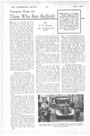
Kerb bumping is another bad habit which puts up the tyre bill. Indulged in often, it may alter the, predetermined, .4-in. toe-in of the front wheels and cause mis-alignment. If this has already happened. it can be remedied by slackening the two pinch bolts, one on each end of the steering tie rod, and turning the rod. Revolving the rod in the same direction as the wheels rotate when the vehicle is moving forward will increase the amount of toe-in. Turning the rod in the opposite direction will decrease it.
The two measurements needed to check toe-in are rather delicate, however, and you may prefer to entrust the adjustment to your dealer, especially as he will be able to check the camber and castor angles at the same time. The camber angle is, of course, the slope of the front Vtheels away from the vertical, i.e., the angle which makes
the distance between the tops of the tyres greater than the distance between the points where they contact with the ground. The castor angle shows the inclination of the tops of the pivot pins towards the rear of the vehicle.
Both angles are extremely small, but they materially affect tyre life: and as most Bedford dealers now have the equipment for measuring them accurately, it is a sensible investment to spend a few shillings to ensure that they are right.
In this page last month, I dealt with brake and brake pedal adjustment, and omitted to mention brake bleeding. This is an important operation when hydraulic brakes develop a "spongy " feeling, and the following notes will, I believe, make both the cause and the cure clear.
Failure to top up the brakefluid reservoir regularly, loose unions on the brake lines, or general rough usage, nfay have let air into the hydraulic braking system. The presence of this air will impair the vigour of the brakes by creating a " spongy " resistance when the pedal is used, and it should be removed by bleeding as soon as possihle. Incidentally, the system should be bled whenever a new pipe or union has been fitted to any part of it.
You will need a glass jar for the job and about a yard of outside diameter thick-walled rubber tubing.
Start by checking all the unions. If you omit to do this, you may be merely pumping out the air already in the system and letting more take its place. Then fill up the brake reservoir, taking care to use only Lockheed fluid.
There is one brake bleeder screw to each wheel. Those for the front brakes are located on the outside of the back plate, just above the connection to the Lockheed brake hose; they are the small hexagons with the tapering nipples similar to ordinary grease nipples. The back bleeder screws, also one to each wheel, are found on top of the wheel cylinders, opposite the point of connection with the brake pipes.
Remove the dust cap from one of the front screws, and slip one end of the rubber tube over the screw. Pour a little Lockheed fluid into the jar and submerge the other end of the rubber tube in it. . Then unscrew the bleeder screw one or two turns.
Expelling Air from System Now get into the cab, depress the brake pedal quickly, and allow it to return without assistance. This will pump the fluid through the system and out into the jar; any air which is present will go with it and will show in. the jar as bubbles. Top up the reservoir to keep it at least three-quarters full, -continue to use the pedal until no more bubbles appear, and then tighten the bleeder screw. Repeat the proce'clure on the other three wheels.
A last thing to bear in mind. The fluid pumped into the jar is full of minute bubbles of air, even if you cannot see them. Let it stand for some considerable time (covering the top of the jar to keep out the dirt) before you use it again in the reservoir.