


A New and Interesting Infinitely Variable Gear
Page 47
Page 48
If you've noticed an error in this article please click here to report it so we can fix it.
The Dellread Automatic Torque Converter which Incorporates an Hydraulic Coupling Having SelfAdjusting Vanes Working in Conjunction with an Epicyclic Reduction Gear. Tests Reveal High Efficiency
THE Dellreacl Gears (Holdings) Co., Ltd., 2, St. Armes Lane, Great Peter Street, London, S.W.1, is better known in general-engineering circles than in the automobile industry. The concern has, however, recently carried out successful experiments with its Epirolic planetary friction gear for private cars, and has now evolved an ingenious hydromechanical torque converter. In this device the power is transmitted through a fluid coupling to an epicyclic drive, of either the friction or positive
gear type, and thence to the propeller shaft, the reduction afforded being determined entirely automatically and shared by the two mechanisms.
lip to now tests have been carried out only with a model (from which the accompanying perspective drawing was made) of about one-third the size that would be required for a light van. They have, however, been most encouraging, and a member of the .staff of this paper recently witnessed a
convincing demonstration of this model.
The efficiency of the device is high, and the temperature of the oil after the tests, which included transmitting 2 h.p., running at maximum r.p.m., loading the output shaft until the motor nearly stalled, exhibiting the braking capabilities of the device and so forth, reached only 45 deg. C. in an atmosphere at 24 deg. C.
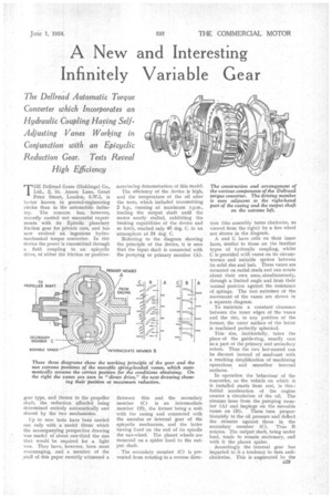
Referring to the diagram showing the principle of the device, it is seen that the input shaft is connected with the pumping or primary member (A).
Between this and the secondary member (C) is an intermediate member (13), the former being a unit with the casing and connected with the annulus or internal gear of the epicyclic mechanism, and the latter having fixed on the end of its spindle the sun-wheel. The planet wheels are mounted on a spider fixed FL? the output shaft.
• The secondary member (C) is prevented from rotating in a reverse direc
tion (the assembly turns clockwise, as viewed from the right) by a free wheel not shown in the diagram.
A and C have cells on their inner faces, similar to those on the familiar types of hydraulic coupling, whilst C is provided with vanes on its circumference and suitable spokes between its solid rim and hub. These vanes are mounted on radial studs and can rotate about their own axes, simultaneously, through a limited angle and from their normal position against the resistance of springs. The two extremes of the movement of the vanes are shown in
a separate diagram. .
To maintain a constant clearance between the inner edges of the vanes and the rim, in any position of the former, the outer surface of the latter is machined perfectly spherical.
This rim, incidentally, takes the place of the guide-ring, usually cast as a part of the primary and secondary rotors. Thus the two last-named can be die-cast instead of sand-cast with a resulting simplification of-machining operations and smoother internal surfaces. '
In operation the behaviour of the Converter, as the vehicle on which it is installed starts from rest, is this: Initial acceleration of the engine creates a circulation of the oil. The streams issue from the pumping member (A) and impinge on the movable vanes on (B). These turn proportionately to the oil pressure and deflect the streams against those in the secondary member (C). 'Thus B rotates. The output shaft, being under load, tends to remain stationary, and with it the planet" spider.
Accordingly the internal gear has imparted to it a tendency to turn anticlockwise. This is augmented by the B29
flow of fluid. The torque thus set up, however, is resisted by the ratchet, with the result that the output shaft is compelled to rotate, at a fraction of the speed of B determined by the epicyclic gear ratio (3 to 1 in the model we inspected). B, it should be realized, is turning at a fraction of the speed of A determined in the main by the shape and setting of the movable vanes. This is automatically controlled, within limits, by the pressure of the oil, itself dependent on the engine speed and the resistance of the output shaft.
We were informed that the overall practicable reduction, on the model, was about 7 to 1, at which the apparatus would run, at maximum engine speed, that is to say full load, for periods of reasonable duration. • The next stage, while the vehicle gains speed, is that the secondary member (C) begins to turn, thus reducing the epicyclie gear reduction. AS the output load diminishes, so does the relative motion between B and C, until the gearing is rotating as a unit. At the same time, the slip between A and B is reduced to the minimum, and the equivalent of direct drive is afforded.
It is obvious that, during this equalizing of the speeds of the three rotors, the vanes will gradually resume their normal positions, under spring pressure. It is actually possible, under favourable conditions, for C to be driven slightly faster than B, thus affording an overdrive.
In order that the oil pressure on the movable vanes may be enabled to turn them on their own axes, they are offset on the studs which carry them, the greater length of blade extending towards the pumping member.
Although there is only a small drag when the power unit is idling, a means for mechanically disconnecting the drive is certainly an asset. This, hOwever, would be incorporated in a separate reverse gear, necessary in any case.
Under ordinary " top-gear " driving conditions, we understand that there is quite a wide range of engine speed and torque within which the apparatus continues to afford a 1-to-1 ratio. The gear acts as a brake pfovided the speed of the output shaft is considerably in excess of that of the input shaft, but when the difference is low a freewheeling effect is afforded.
A method of permitting expansion of the .fluid has been evolved, but we are not permitted to disclose its nature as it has not yet been fully patented.
We are informed that for privatecar work the Epirolic friction gear would be employed instead of the positive epicyclic mechanism, but that on commercial vehicles the type would be optional.