


THE 31 TON AND 5 TON DE DION CHASSIS.
Page 18
Page 19
Page 20
If you've noticed an error in this article please click here to report it so we can fix it.
Two Models Incorporating the Famous De Dion Features of Intermediate and Differential Gear Slung from Frame, and Internal Gear Final Drive.
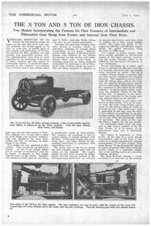
VEHICLES PRODUCED BY the famous De Dion-Bouton works are known as the cars that never wear out, and certainly this would appear to be true, as, even now, in certain parts of this country, and particularly in France, the earliest De Dion products are still running, and apparently running well. Few manufacturers have had so much
• experience in the production of all types of motor vehicles—and this appliesto commercial vehicles, as omnibuses manufactured by this company were running both in France and in this country, many years ago, and are still running in Paris. The company have always had a name for good design and accurate workmanship, this reputation has been maintained, and will, we consider, be maintained in the future.
Two models are now marketed in this country. They are the 3 ton and 5 ton
chassis. As the 5 ton chassis differs only in strength of construction from the 3; toriner, we propose. to deal mainly with the latter in this article. Considerable numbers of both types are also being
sent to India, Australia, South Africa, and other of our Colonial possessions.
Amongst the users here, Cerebos, Ltd., have several 5 tonners, which, incidentally, maintain an average petrol consumption of 7.5 m.p.g. Approximately 3,000 vehicles of De Dion manufacture were utilized by the French Government for war service, and similar chassis fitted with water tanks or sweeping apparatus are being employed successfully for municipal work in Paris. Apart from-ordinary goods conveyance, they are being employed in England to a considerable extent as chars-I-banes. The company are arranging to have a certain number of chassis equipped with Michelin welded steel wheels and pneumatic tyres, and these should be particularly serviceable in connection with char-i-basics work.
The power unit of the 3i ton model has four cylinders cast in pairs with the valves on the nearside. The tappet guides are held down in pairs by bridge pieces, and the exposed nortions of the valve-operating mechanim are enclosed
by pressed steel covers, each being held in position by a neat, spring locking device. The bore and stroke of the engine are 100 mm. and 140 mra. respectively, the power developed being 25 bhp. at 1,400 ap.m.
This engine is rather smaller than those usually provided on British-built chassis of the same carrying capacity, but the power certainly seems to be sufficient, and the petrol consumption is very satisfactory.
Forced lubrication by a rotary gear pump is employed for the main and big end bearings, the small ends and pistons being lubricated by splash. The oil is. carefully filtered during its passage, and the filter can be withdrawn for cleaning purposes. The magneto is driven direct from the timing gears, andat the ether side the magneto driving pinion spindle carries a belt pulley which drives a large fan contained in the centre of the Solex radiator. A spring jockey pulley maintains the necessary tension in the flat, leather belt. A governor of the centrifugal type contained in the timing gear case operates direct on the throttle.
The .Solex radiator is now fairly well known in this country. It is of the tubular type, the tubes being formed into a circle, in the hollow centre of which IS situated the fan. The small water tank is positioned at the top, and the frtint of the radiator is protected by an aluminium casting, the appearance of which CPA be seen from the photograph which we reproduce. The centre of this casting forms a support for the fan spindle.
An interesting point about the magneto is that it is a product of the De Dion Works. It is, of course, of the: high-tension type, and is beautifully finished.
The .engine is supported at three points : at the rear on a stout dipped cross-member, and at the front in the " centre of a similar pressed-steel channel cross-member; it is thus isolated from frame flexion. It can be perfectly alignect by means of special bolts fitted with .adjusting collars in a somewhat similar way to the levelling screws of a precision weighing Machine.
The large flywheel contains a clutch consisting of a steel disc on the gearbox shalt, which is gripped between two bronze discs on the crankshaft; one of these bronze discs slides along the Crankshaft, and helical springs, spaced regularly round the clutch, force the
three discs into contact. The clutchoperating mechanism is of neat design. It consists of a collar operating through lour levers, which push in pins project-' ing through the casing of the clutch.. These pins take the pressure of the springs, thus freeing the discs.
The drive is taken through a nonflexible coupling to the four-speed-and• reverse gearbox; the latter is also three:. point suspended; at the front from a slightly arched cross-member, and at the rear from a straight cross-member.
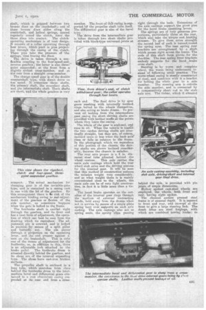
The change speed gear is of the double countershaft type, with direct drive on top speed. It comprises three shafts, the primary shaft, the secondary shaft, and the intermediate shaft. These shafts are short, end the whole gearbox is-very compact. The actual mechanism for changing gear is of the invisible-gate type, and is contained in a easing cast in one with the lid of the gearbox. By this arrangement there is .1, -risk of the mechanism binding owing to mal-adjustment of the gearbox or flexion of the side member, as sometimes happens when the gate is bolted to thtframe. The footbrake shaft is carried right through the gearbox, and its front end has a neat form of adjustment, the operation of which can best be seen from the drawing which We reproduce. The adjustment pin is screwed, and is locked in position by means of a split pillar and butterfly nut. The pin passes through a projection on the operating lever, and its end presses against a
cam on the .brakeshaft. This is Only one of the means of adjustment for the footbra,ke, as, in addition to this, there is an adjustable fork attached to the
brake pedal. The footbra,ke drum is situated directly behind the gearbox, and its shoes are of the internal expanding type. The shoes have cast-iron friction surfaces.
The propeller shaft is enclosed in a long tube, which stretches from close behind the fontbrake drum to the intermediate bevel and differential gears contamed in a east abrinininre casing enspended at its rear end from a cross
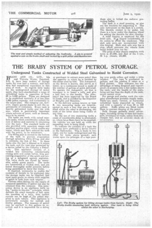
member. The front of thig easing is. supported b7 the propeller shaft tube itself. The differential gear is also of the bevel type. The'drive from the intermediate gear is taken through two short shafts provided with block-type universal joints at each end. The final drive is by spur
gears meshing with internally toothed rings boltedto the wheels themselves, and also acting as brake drums. To prevent oil leaking from the intermediate gear casing the short driving shafts are provided -with leather muffs at the points where they leave the casing.
The whole of the gear is enclosed, and runs in oil. When the vehicle is loaded the two cardan driving shaTts are practically straight, but they are, of course, inclined more or less when the back axle" rises or falls in relation to the frame. In the photograph which we reproduce of this portion of the chassis, the driving shafts are shown inclined considerably, because the chassis is unladen. The rear axle proper is a 4 in, diameter steel tube situated behind the wheel centres. This axle carries the main axle castings which hold the rear wheel stub axles and the driving pinions for the internal gear. It will be seen that this method of construction reduces the unladen weight very considerably, and as what weight there is is mainly concentrated close to the wheels, the main axle can be of very light construction, in fact it is little more than a tiebar.
The hand brake operates on the outsides of the internal gear rings through the medium of external contracting bands, held away from the drumswhen nut in service by means of a single plate spring bent over supports on each axle casting. The axle castings also act as spring seats, the spring clips passing
right through the beds. Extensions of the axle castings support the pivot pins for the hand brake operating -levers.
The springs are of very generous proportions, particularly those at the rear, which also take the torque and.brakhig stresses. To give them extra strength the second leaf of each is turnekroand the spring eyes. The rear spring rear brackets are strengthened by a shaft which passes right across the frame. The ends of this shaft form pivots, for the shackles. The rear spring front brackets embody supports for the hand brake cross shaft.
Steering is by worm and complete wheel, the worm being underneath instead of following usual practice. The worm-wheel easing is stoutly constructed of steel, and combines with it a ...bracket for bolting the whole gear to a side member. The steering arm is -outside the side member, and is connected by a comparatively short rod to the stub axle arm, The tiebar, which it situated
behind the axle, is provided with pin joints of ample dimensions. follow spoked cast-steel wheels are employed, the wheels, both front and rear, having eight spokes.
The channel section pressed steel frame is of unusual depth. It is tapered to front and rear, and inswept at the front to give a large steering lock. The dumb irons are steel forgings, with which are combined towing hooks; to
them also is bolted the radiator protecting buffer.
The clash is a steel pressing, as. also are the brackets for supporting it. The only instrument on the dash is a switch. The throttle =teal is by pedal, buts there is a lever under the steering wheel 'for setting the throttle for slow running.
A solid forging is employed for the front axle. It jis dipped considerably at its centre to avoid the crankcase. The stub axle jaws.. are incorporated with this forging. Each stub axle arm has a stop, which prevents the wheels from being locked over too far.
The price of this chassis complete with tyres is £1,050, and that of the 5 .ton, 35 h-p. chassis, £1,250.