 1
1 2
2 3
3 4
4 5
5 6
6 7
7 8
8 9
9 10
10 11
11 12
12 13
13 14
14 15
15 16
16 17
17 18
18 19
19 20
20 21
21 22
22 23
23 24
24 25
25 26
26 27
27 28
28 29
29 30
30 31
31 32
32 33
33 34
34 35
35 36
36 37
37 38
38 39
39 40
40 41
41 42
42 43
43 44
44 45
45 46
46 47
47 48
48 49
49 50
50 51
51 52
52 53
53 54
54 55
55 56
56 57
57 58
58 59
59 60
60 61
61 62
62 63
63 64
64 65
65 66
66 67
67 68
68 69
69 70
70 71
71 72
72 73
73 74
74 75
75 76
76 77
77 78
78 79
79 80
80 81
81 82
82 83
83 84
84 85
85 86
86 87
87 88
88 89
89 90
90 91
91 92
92 93
93 94
94 95
95 96
96 97
97 98
98 99
99 100
100 101
101 102
102 103
103 104
104 105
105 106
106 107
107 108
108 109
109 110
110 111
111 112
112 113
113 114
114 115
115 116
116 117
117 118
118 119
119 120
120 121
121 122
122 123
123 124
124 125
125 126
126 127
127 128
128 129
129 130
130 131
131 132
132 133
133 134
134 135
135 136
136 137
137 138
138 139
139 140
140 An American Disc Brake
Page 104
If you've noticed an error in this article please click here to report it so we can fix it.
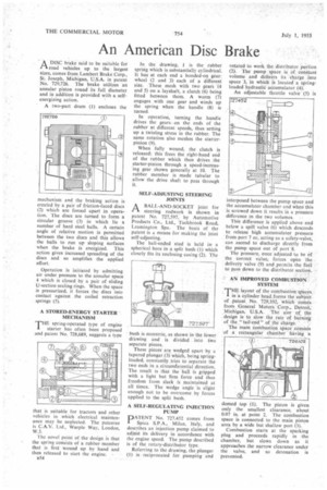
ADISC brake said to be suitable for road vehicles up to the largest sizes, comes from Lambert Brake Corp., St, Joseph, Michigan, U.S.A. in patent No. 729,726. The brake utilizes an annular piston round its full diameter and in addition is provided with a selfenergizing action.
A two-part drum (1) encloses the mechanism and the braking action $ created by a pair of friction-faced discs (2) which are forced apart in operation. The discs are turned to form a circular groove (3) in which lie a number of hard steel balls. A certain angle of relative motion is permitted between the two discs and this allows the balls to run up sloping surfaces when the brake is energized. This action gives increased spreading of the discs and so amplifies the applied effort.
Operation is initiated by admitting air under pressure to the annular space 4 which is closed by a pair of sliding U-section sealing rings. When the space is pressurized, it forces the discs into contact against the coiled retraction springs (5).
A STORED-ENERGY STARTER MECHANISM
THE spring-operated type of engine starter has often been proposed and patent No. 728,689, suggests a type
that is suitable for tractors and other vehicles in which electrical maintenance may be neglected. The patentee is C.A.V. Ltd., Warple Way, London, W.3.
The novel point of the design is that the spring consists of a rubber member that is first wound up by hand and then released to start the engine.
B54
In the drawing, 1 is the rubber spring which is substantially cylindrical. It has at each end a bonded-on gearwheel (2 and 3) each of a different size. These mesh with two gears -(4 and 5) on a layshaft, a clutch (6) being fitted between them. A worm (7) engages with one gear and winds up the spring when the handle (8) is turned.
In operation, turning the handle drives the gears Oil the ends of the rubber a t different speeds, thus setting up a twisting stress in the rubber. The same rotation also meshes the starterpinion (9).
When fully wound, the clutch is released; this frees the right-hand end of the rubber which then drives the starter-pinion through a speed-increasing gear shown generally at 10. The rubber member is made tubular to allow the drive shaft to pass through It.
SELF-ADJUSTING STEERING JOINTS
I-1 A BALL-AND-SOCKET joint for
steering rodwork is shown in patent No. 727,597, by Automotive Products Co., Ltd., Tachbrook Road, Leamington Spa. The basis of the patent is i means for making the joint self-adjusting.
The ball-ended stud is held in a spherical bore in a split bush (I) which closely his its enclosing casing (2). The bush is eccentric, as shown in the lower drawing and is divided into two separate pieces.
These pieces are wedged apart by a tapered plunger (3) which, being springloaded, constantly tries to separate the two ends in a circumferential direction. The result is that the ball is gripped with a light but firm force and thus freedom from slack is maintained at all times. The wedge angle is slight enough not to be overcome by forces applied to the split bush.
A SELF-REGULATING INJECTION ATENT No. 727,452 comes from Spica SPA., Milan, Italy, and describes an injection pump claimed to adjust its delivery in accordance with the engine speed. The pump described is of the rotary-distributor type. Referring to the drawing, the plunger (1) is reciprocated for pumping and rotatedto work the distributor portion (2). The pump space is of, constant volume and delivers its charge into space 3, in which is located a Springloaded hydraulic accumulator (4): An adjustable throttle valve (5) is interposed between the pump space and the accumulator chamber and when this is screwed down it results in a pressure difference in the two volumes.
This difference is applied above and below a spill valve (6) which descends to release high accumulator pressure from port 7 or, acting as a safety-valve, can ascend to discharge directly from the pump space out of port 8.
The pressure, once adjusted to be of the correct value, forces open the delivery valve (9) and permits the fuel to pass down to the distributor section.
AN IMPROVED COMBUSTION.
SYSTEM . THE layout of the combustion spacs.in a cylinder head,forms the subject of ,pateot No. 729,102, which comes from General Motors Corp., Detroit, Michigan, U.S.A. The aim of the • design is to slow, the rate Of burning of the "tail-end" of the charge. ' The main combustion space _consists of a rectangular chamber having 'a
domed top (1). The piston is given only the smallest clearance, about 0.07 in, at point 2. The combustion space is connected to the main piston area by a wide but shallow port (3).
Combustion starts at the sparking plug and proceeds rapidly in the chamber, but slows down as it approaches the narrow clearance under the valve, and so detonation is prevented.