


AN INTERNAL-COMBUSTION TURBINE.
Page 46
If you've noticed an error in this article please click here to report it so we can fix it.
A Résumé of Recently Published Patents.
INVENTIONS dealing with the design of internal-combustion turbines have not of late been so prolific as hi the past, and this circumstance lends particular interest to patent
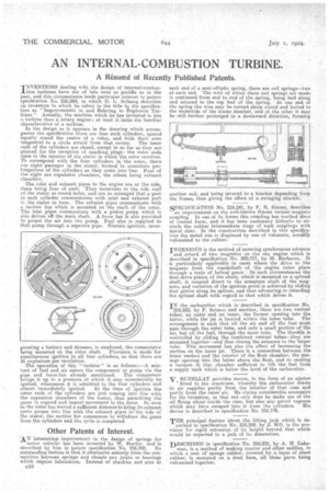
specification No. 216,384, in which L. &Liman describes an invention to which he refers in the title to the specification as "Improvements in and Relating to Explosion Turbines." Actually, the machine which lie has invented is less a turbine than a rotary engine; at least it lacks the familiar characteristics of a turbine, In the design as it appears in the drawing which accompanies the specification there are four such cylinders, spaced equally round the centre of a rotor, and with their axes tangential to a circle struck from that centre. The inner ends of the cylinders are closed, except in so far as they are pierced for the reception of sparking plugs : the miter ends open to the interior of the stator in which the rotor revolves. To correspond with the tour cylinders in the rotor, there are eight passages in the stator, formed to constitute prolongations of the cylinders as they come into line. Four of the eight are expansion' chambers, the others being exhaust chambers.
The inlet and exhaust pipes to the engine are at. the side, there being four of each. They terminate in the side wall of the. stator as round holes, and are so arranged that a port in, each cylinder communicates with inlet and exhaust port, in the stator in turn. The exhaust pipes communicate with is Suction fan which is mounted on the shaft of the rotor. The inlet pipes communicate with a piston punip which is elm() driven off the main shaft. A force fan is also provided to propel the air into the pump. Fuel also is supplied to that pump through a separate pipe.' Electric ignition, incor porating a battery and dynamo, is employed, the commutator being mounted on the rotor shaft. Provision is made for simultaneous ignition in all four cylinders, so that there are 16 explosions per revolution. •
The operation of this " turbine " is as follows :—A mixture of fuel and air enters the. compressor or pump via the
pipe and force-fan already mentioned. The compressor brings it -up to a pressure at which it may economically be ignited, whereupon it is admitted to the four cylinders and almost immediately ignited. At the time of ignition the outer ends of the cylinders are just coming into line with the expansion chambers of the stator, thus permitting the gases to expand and impart movement to the rotor. So soon ha the rotor has moved a sufficient distance to bring its exhaust ports proper into line with the exhaust pipes in the side of the stater, the suction fan commences to withdraw the gases from the cylinders and the cycle is completed.
Other Patents of Interest.
AN interesting, improvement in the design of springs for motor vehicles has been invented by W. Starley, and is
described by him in patent specification No. 216,292. Its outstanding feature is that it eliminates entirely from the connections between. springs and chassis any, .joints or bearings which require lubrication. Instead of shackles and pins at C59 • each end of a semi-elliptic Spring, there are coil springs—two at each end. The wire of which these coil springs are made is continued from end to end of the spring, being laid along and secured to the top 'leaf of the spring. At one end of the spring the wire may be turned sharp round and bolted to the underside of the frame Member, and at the other it may be still further prolonged in a downward direction, forming another coil, and being secured to a bracket depending from the frame, thus giving the effect of a swinging shackle.
SPECIFICA_TION No. 216,241, by E. R. Simms, describes
an improvement on the well-known Simms vernier magneto coupling. In one of its forms this coupling has toothed discs of conical form, and it has been customary hitherto to en-, circle the rubber intermediate rings of such couplings With inetal rims. In the construction described in this specie.. tion the metal rim is displaced by one 'of vulcanite, actOWY vulcanized to the rubber.
INGENIOUS is the method of ensuring synchronous advance and retard of two magnetos on the one. engine which is described in specification No. 209,717, by M. Barbarou. It is partioularIy applicable in eases where the drive to the magneto from the crankshaft of the engine takes place through a train of helical gears. In such circumstances the final-drive pinion of the chain, which is mounted on a splined shaft', is coupled direct to the armature shaft of the magneto, and variation of the ignition point is achieved by sliding that pinion along its splines, and thus advancing or retarding the splined shaft with regard to that which drives it.
IN the carburetter which is described in specification No.
216,233, by P. Salmon and another, there are two venturi tubes, an outer mid -an inner, the former opening into the latter, while the jet is located within the inner tube. The arrangement is such that all the air and all tile fuel must pass through the outer tube, and only a small portion or the air, but all the fuel, through the inner tube. The throttle is controlled by _sliding the combined venturi tubes—they are mounted together—and thus closing the -entrance to tbe larger tube. This movement has also the effect of increasing the suction on the inner jet. 'There is a connection between the inner venturi and the interior of the float chamber, the passage opening into the latter above the float, and so causing a vacuum in that chamber sufficient to lift the fuel from a supply tank which is below the level of the carburetter.
VRUDELLAT provides means, in the form of an ejector • fitted to the crankcase, whereby the carburetter draws in air supplies partly from the interior of that case and partly from the outer air. He claims considerable economies for his invention, in that not only does he make use of the oil flying about inside the case, but also any petrol vapours which may have escaped• into it from the cylinders. His device is described in specification No, 216,176.
THE principal feature about the lifting jack which is de,. scribed in specification No. 216,269, by J. Hill, is the provision for rapid extension of its height beyond that which would be expected in a jack of its dimensions.
DESCRIBED in specification No. 216,331, by A. H. Lakeman, is a method of making tractor and other saddles, in which a seat of sponge rubber, covered. by a layer of sheet rubber, is mounted on a steel base, all three parts being vulcanized together. •