


ANOTHER BID FOR UNDERTYPE SUPREMACY.
Page 26
Page 27
Page 28
If you've noticed an error in this article please click here to report it so we can fix it.
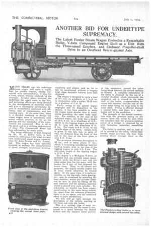
The Latest Fowler Steam Wagon Embodies a Remarkable Boiler, V-twin Compound Engine Built as a Unit With the Three-speed Gearbox, and Enclosed Propeller-shaft Drive to an Overhead Worm-geared Axle.
MANY YEARS ago the undertype steam wagon had quite a vogue, but, for certain reasons, chiefly concerned with inaccessibility, it was, for a time, almost entirely replaced by the overtype. In later years, however, the unde-rtype has again come to the fore, and increasing efforts are being devoted to the developmentof machines which will give a thoroughly satisfactory degree of accessibility combined with efficiency, ease of maintenance, and low running costs. At the same time, there is a decided tendency to design the steam wagon more in accordance with petrol vehicle practice, so far as the gearing and the remainder of the transmission are concerned. This is all to the good, and is a striking endorsement of what The Commercial Motor has been advocating for many years.
The latest undertype is that designed by Mr. W. J. Lewin (who is well known in connection with what we may term modernized steam wagon construction) for John Fowler and Co. (Leeds), Ltd. This wagon has been specially designed to embody the characteristics of speed, strength, economical working,
simplicity and silence, and, so far as can be ascertained without a lengthy tbe>se desirable features have been obtained.
The wagon is designed to carry a load of 6-7 tons on gradients of .1 in 6, or, in conjunction with a trailer, 10-12 tons on a gradient of 1 in 10.
Partly owing to the special engine employed and its disposition in the chassis, it has been possible to make the wagon much shorter than is usual, whilst providing the same body capacity. For instance, in the case of the standard wagon, the body has a length of 14 ft. 6 ins. on a wheelbase of 11 ft., whilst in the tipping wagon the body is 12 ft. 'long and the wheelbase 9 ft. 6 ins. The track is 6 ft. 6 ins, to the outside edges of the tyres. Ample room 1S given in the cab, but, in spite of this, the distance from the back of the cab to the face of the front plate is only 5 ft. 5 ins.
The minimum clearance throughout is 12 ins., and in many places 17 ins., which is surprising considering that the loading height, even in the case of the tipping wagon, is only 4 ft. 3 ins. The maximum length of the tipping wagon Is 17 ft. 8 ins.
The engine is a 90-degree V-twin, so mounted that one cylinder comes immediately under the driver's seat and the other under that for the mate, with the bunker for 8 cwt. of fuel disposed between them. Thus, to all intents and purposes, the engine merely makes use of what would otherwise be wasted space. At the same time, it is quite, accessible, as the big-ends, valve gearing, etc., may be examined by removing the base chamber, whilst the cylinder heads can be seen at once by lifting off the seat cushions and the asbestos mattress which is placed over each cylinder. Incidentally, no trouble has been experienced owing to the seats being heated, for, apart from the asbestos protection, there is an air space, and the combined effect is quite satisfactory..
We will now go right through the description of the vehicle, starting at the front end with the boiler.
This is a vertical type of most unusual construction, for the water is contained in a space between the domed firebox. and the concave lower portion
of the srnokebox, curved fire tubes , being fitted between the curved surfaces so formed. A complete submersion of the tubes is obtained by the use of a circular chamber which surrounds the smokelaox and is riveted -to the outer. shell of the boiler, communication between this chamber and the rest of the water space being via large holes in the outer shell. Firing is effected through a central tube, and there is a super heater coil in the smokebox. • The strength of the darned construction with the pressure acting on the convex faces can easily be seen when one considers that the pressure-resisting power of a bridge is obtained by an arch formation somewhat resembling this.
The boiler is stayless, and no load at all is carried by the tubes, whilst their curved shape prevents the heat from passing direct through them to the
smokebox, as it is thrown against the inner surfaces, this considerably improving the efficiency of the heat extraction.
The expansion chamber at the top of the boiler also acts as a steam space, which obviates priming and reduces the possibility of sudden fluctuations in water level.
Screwed pings and mud holes are provided for washing out, and, in addition, the whole interior of the boiler and tubes. can be dropped for inspection or
repair by unbolting two joints, one at the top and one at the bottom.
Another excellent feature of this boiler is that the smokehox dome is hingedon the exhaust pipe, and, by releasing four special bolts, the whole top can be swung on its hinge, thus exposing the superheater coils and giving access to the tubes for brushing through or replacement.
There are 108 curved „ fire tubes of 11 ins, diameter, which are quite unaffected by gradients. The effective heating surface of the boiler is 85 square ft., and that of the superheater -21 square ft., whilst the grate area is 3.8 square ft. The water capacity at half gauge is 48 gallons., The plate thicknesses may be .of interest to some of our readers. That of the firebox is in,, whilst the top tube
plate.is in., and the shell in_ The. working pressure is 225 lb„ and the t est pressure .315 lb. The water is supplied by a plunger-type pump driven from an eccentric formed in one with the slowspeed gearwheel : this is supplemented by an ordinary type of steam injector.
We have already mentioned theengine. We will now amplify our remarks in this connection. It is of the compound type with piston -valves and Hackworth reversing valve gear; the H.P. cylinder is 4.1 ins: diameter, and the L.P. 7 ins., the stroke being 8 ins., giving an I.H.P. of 55 at normal .speed.
Heavy-duty roller bearings are utilized for the crankshaft and connecting rods, and the method of fitting those for the big-ends is of interest. The crankshaft is formed in two parts, in addition to the separate flyviheel, which is held in position by. setscrews, some of which have locking plates, whilst in others the heads are in dovetailed holes, afterwards filled with lead. The flywheel side of the crankshaft is fortnisd " with .a spigot, this being
tapered; splined, and having a screwed end for a tapered nut. The other half. of ,the crankshaft is bored out to suit the tapers of the spigot and nut, and cut to suit the splines. It does not only, give a double wedging effect, but is easy to align because of the splines. Each connecting rod is offset at the fork, and is provided with two bearings, the forks being intersected. A feature of the valve gearing is the bobbin-type cylindrical slides, which do not have a tendency to seize as is sometimes found with the flat type, and 11 ins, is allowed for valve travel. Each piston has three cast-iron rings of the usual Ramsbottom type, and the bodies are dropped stampings. Ample wearing surface is provided in the cylindrical slippor-type cross-heads, which have a diameter of 51 ins.
A mechanical lubricator is carried on the footplate, this being worked from the L.P. valve spindle by a friction device, by which the reciprocating motion
of the connecting link is turned into rotary one, all external ratchets being dispensed with, which results in slow running, efficiency and long life of the working parts, these consisting of one lever and two pins. Each cylinder is provided with a combined relief valve and drain tap, the-relief effect boing obtained hy,alcam device which slightly opens the' valve. Additional power for starting or other reasons can be obtained by the use of a by-pass valve which admits H.P. steam to the L.P. cylinder.
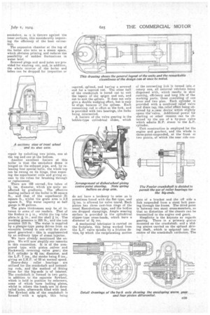
Unit construction is employed for the engine and gearbox, and the whole is three-point-suspended, at the front at two points, of which the near side eon
slats of a bracket and the off side a link suspended from a stout bolt passing through the frame. The third point is between two stout cross-members, so that no distortion of the chassis can be transmitted to the engine and gears.
Simplicity is the keynote as regards gearing. There is A primary 'pinion mounted on the crankshaft: and A ' sliding pinion carried on the splined driving shaft, which is spigoted into the centre of the crankshaft extension. The
pi iinary pinion is in constant mesh with a large pinion on the layshaft for direct drive. The sliding pinion is moved forward until the teeth cut in its interior mesh with the teeth of the crankshaft pinion. Far second gear the sliding pinion is moved back and engages. with a wheel on the layshaft, whilst for the third gear the movement back is continned until the dogs on the sliding pinion engage with those on an independent slaw-speed gear, which is in constant mesh with the third pinion on the layshaft. The gearing provided gives road speeds in the proportion of 3, 8 and 12 m.p.h.. although much higher speeds than these can be obtained if desired.
Behind the gearbox is a split casing forming the spherical housing for the 2rant end of the combined torque and thrust member. Within this spherical chamber is -a ring-type universal joint with case-hardened pins. Both portions of the universal joints are carried on splines, and there is a spliced plunger joint at the end of the propeller. shaft.
The leach axle more closely resembles
certain of the types utilized for petrol vehicles than is the ease with any other steam wagon which we have yet seen, and it is unique in that the final drive is by overhead worm gear. This warm gear is the most up to date evolved, as it is of the enveloping type, designed by Bostack and Bramley, to which we _recently drew attention in The Commercial Motor. A four-bevel pinion differential and splined axle shafts to the rear-wheel hub caps complete the resemblance.
The axle casing itself is made of 40too forged steel. It is of the pot type, and is arranged so that the whole of the final drive and differential gearing can ha lifted out without removing the road wheels.
An unusual system is employed for the braking. A.24-in. drum is employed for each rear wheel, and in this are two shoes, the expanding of which is effected by two separate cams, one operated by the hand-brake lever and the other by a pedal : thus the two methods of control of the shoes are completely independent. The handbrake lever, instead of being attached direct to the shaft, has hinged on it a pawl. engaging with a ratchet, wheel on the brake cross-shaft, and there is also a locking pawl pivoted on the brakequadrant support. With this arrangement, if one movement of the lever proves insufficient, a second movement can be made. It must also be remembered that the reverse can be utilized as a powerful brake.
Tubular cast-steel-spoked wheels are employed all round, but those at the front are dished to give centre-point steering.
Unusual construction is also to be found in the front axle, as the stub axles are carried beneath the main axle, thus giving a big clearance. The steer
, ing gear is of the screw-and-nut type, completely enclosed and running in oil, giving a lock of 42 degrees and a turning circle of 36 ft. to 38 ft. A fork, spliced into the end of the drop arm, meshes with the nut. The drop arm floats between two compression springs on the connecting link, thus cushioning road shocks.
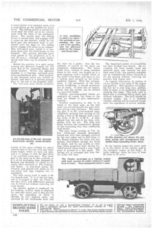
The main frame consists of 7-in. by 3-in.rolled-steel channels thoroughly braced and with their strength retained by the care taken not, to drill holes in the flanges between the front and rear springs, semi-elliptic springs are fitted all round, and we can testify to their, easy riding properties after having travelled several times round a very rough. piece of ground at a fair speed. The springs are so arranged that they flatten under full load. The important matter of accessibility has been studied very closely. By uncoupling the front dardan joint and spherical joint, and running the axle back some 2 ins., the gearbox end-plate can be unbolted and access obtained to all the gearing Without removing the gearbox and engine unit.
As regards lubrication, 4 gallons of oil are carried in the sump of the engine and gearbox. This quantity will probably last for a very long time, particularly as there is no possibility of water. reaching the sump. The back axle is fitted with a combined filling elbow and oil-level indicator. The level should be checked weekly, but it is doubtful whether refilling will be required except after the expiration of several months.
. In the tipping wagon the water tank ii in the centre of the vehicle, and in the standard wagon at -the baek: It holds sufficient water for runs of from 25 miles to 35 miles.