


Patents Completed.
Page 22
If you've noticed an error in this article please click here to report it so we can fix it.
Complete specifications of the following patents will be sent to any address in the United Kingdom upon receipt of eightpence per copy at the Sales Branch, Patent Office, Holborn, W.C.
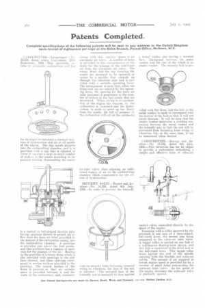
CARBURETTER.---Longuemare.--No. 23,836. dated, under Convention. 28th September, 1901:I.—This invention relates to automatic carburetters and has
for its object to maintain a constant MINture of hydrocarbon aind air at all speeds of the engine. The fuel nozzle projects into the carburetting chamber, and it is provided with a cap that is adapted to cover or uncover a large or small number of orifices in the nozzle according to its position thereon. Surrounding the nozzle
is a conical or bell-shaped throttle tube having openings therein to permit air to flow from the main air inlet, provided in the bottom of the carburetter casing, into the carburetting chamber. A partition is provided just above the fuel nozzle, and this partition has a number of openings for the passage of the air. Resting on the partition is a rotary drum which is also provided with openings in the side faces thereof, and these openings correspond in section to those provided in the partition. The curved surface of the drum is grooved so that an annular space is provided between it and the walls of the carburetter, and, common;
eating with this annular space is au automatic air valve. A number of holes is provided in the circumference of the drum for the passage of the additional air from the automatic air valve. The rotary drum and the cap covering the nozzle are arranged to be operated in unison by a spindle that extends up through the induction pipe and is provided with a suitable operating lever. The arrangement is such that, when the drum and cap are rotated by the operating lever, the opening for the main air inlet increases in proportion to the number of orifices in the fuel nozzle that are uncovered. -When, owing to an acceleration of the engine the vacuum in the carburetter is increased and the hydrocarbon is made to spurt up too freely from the nozzle, the fall of pressure in the carburetter will act on the automatic air-inlet valve, thus allowing an additional supply of air to the carburetting chamber which compensates for the excess of hydrocarbon.
SECURITY BOLTS.—Baxter and Another.—No. 14,200, dated 4th July, 1908.—In order to prevent the butterfly
nuts on security ho Is becoming loosened owing to vibration the face of the nut is serrated. The serrated face of the butterfly nut is arranged to bear against a metal washer also haying a serrated face. Interposed between the metal washer and the rim of the wheel is an elastic washer. The security bolt is pro
vided with fiat faces, and the hole in the metal washer is made to correspond with the section of the bolt so that it will not rotate thereon. It will be seen that the elastic washer maintains a yielding connection between the metal washer and the butterfly nut-, so that the nut will be prevented from becoming loose owing to vibration, but, at the same time, it can be unscrewed when desired.
CARBURETTER.—Murray and Another.—No. 14,198, dated 4th July, 1908.—This invention has for its object to provide a carburetter embodying a simple and effective form of extra-air control valve, controlled directly by the speed of the engine. Engaging with a collar operated by the governor is one arm of a three-armed, bell-crank lever, the second arm being connected to the extra-air inlet valve. A tappet roller is carried on one link of a well-known floating-lever device, and this link is connected to the third arm of the bell-crank lever. This tappet roller bears against the end of the spindle carrying both the throttle and main-air valves. The amountof air required at lowest engine speed is provided for by a number of small holes surrounding the extra-air inlet valve. As the speed of the engine increases the extra-air valveis gradually opened.