


Independent Rear Suspension
Page 60
If you've noticed an error in this article please click here to report it so we can fix it.
PATENT No. 823,580 covers .independent rear suspension by universally jointed half-shafts and leaf springs. The axles swing in an arc as they rise or fall, altering their effective length. A method of spring attachment to accommodate this variation is the subject of the patent. (Vauxhall Motors, Ltd., Luton, Beds.)
The spring (1) carries a V-shaped bracket incorporating two bores (2). The half-shaft is fitted with a bracket (3) which is joined to the spring bracket by esilient rubber bushings as shown generally at 4.
The inner sleeve of each bushing is extended outwards to carry a nylon sleeve. This allows the brackets to move relative to each other to accommodate the change in effective length. Any angular deflection is dealt with by the rubber bushes. Rubber seals prevent the ingress of dirt between the sliding surfaces.
POWER STEERING MECHANISM I N a powered steering design shown in patent No. 823,602 manual effort is transmitted through bevel gears, one of which rocks sideways to operate the hydraulic control valve. (Zahnradfabrik Friedrichshafen A.G., Friedrichshafenam-Bodensee, Germany.)
The steering column (1) is joined to a bevel gear (2) through a simple universal joint (3). The mating bevel is fixed to the steering worm (4) which actuates the drop-arm (5) via a toothed roller (6). The roller fork is extended on the other side of the drop-arm axis to carry another roller (7).
When the column is turned manually the first bevel attempts to roll around the second one. The universal joint permits this to happen, causing one or other of a pair of hydraulic control valves (8) to open. There are four valves but only two are shown. A stop (9) prevents excessive de-meshing of the bevel teeth. The valves control the flow of fluid to a pair of hydraulic rams ((0) which augment the manual effort applied to the drop-arm.
SMOKE PREVENTION
PATENT No. 823,652 describes an injection pump attachment that will automatically adjust the maxim-um rack
setting for fuels of different gravities to prevent exhaust smoking. (Esso Research and Engineering Company, Elizabeth, New Jersey, U.S.A.) The drawing shows in a diagrammatic form how the device functions. A float chamber is attached to the injection pump and maintains a constant fuel level by continuous fuel flow through a restricted inlet (1) and an overflow port (2).
The float assembly (3) is linked to a wedge (4) which is raised or lowered according to the density of the fuel in use. The face of the wedge forms a full-load stop for the injection pump rack (5). When a heavier fuel is used the float rises and the wedge descends, causing the stop face to move to the right and reduce the charge. A screw (6) on the other wedge provides initial adjustment.
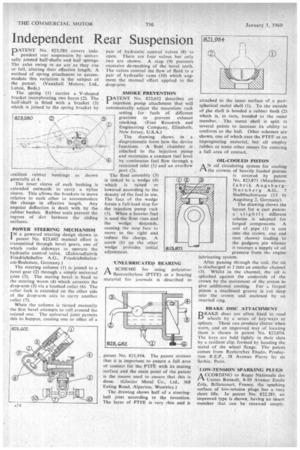
-UNLUBRICATED BEARING A SCHEME for using polytetrar-I fluoroethylene (PTFE) as a bearing material for journals is described in patent No. 821,954. The patent stresses that it is important to ensure a full area of contact for the PTFt, with its mating surface and the main point of the patent is the means used to ensure that this is done. (Glacier Metal Co., Ltd., 368 Ealing Road, Alperton, Wembley.)
The drawing shows half of a steeringball joint according to the invention. The layer of PTFE is very thin and is attached to the inner surface of .a part spherical metal shell (1). To the outside of he shell is bonded a rubber bush (2) which is, in turn, bonded to the outer member. The metal shell is split at several points to increase . its ability to conform to the ball. Other schemes are shown, one of which.uses the PTFE as an impregnating material, but all employ rubber or some other means for ensuring a full area of contact.
OIL-COOLED PISTON
AN oil circulating system for cooling the crowns of heavily loaded pistons is covered by patent No. 823,871 (Maschinenfabrik AugsburgNurnberg A.G., 7 Stadtbachstrasse (13 b) Augsburg 2, Germany).
The drawing shows the layout for a cast piston: a slightly different scheme is adopted for forged components. A coil of pipe (I) is cast into -the crown, one end (not shown) leading to the gudgeon, pin whence it receives a supply of oil pressure from the engine lubricating system.
After passing through the coil, the oil is discharged at 2 into an annular channel (3). Whilst in the channel, the oil is splashed against the underside of the crown by the movement of the piston to give additional cooling. For a forged piston a machined groove is cut deep into the crown and enclosed by an inserted ring.
BRAKE DISC ATTACHMENT DRAKE discs are often fixed to road Li wheels by a series of key-ways or splines. These can produce clatter when worn, and an improved way of locating them is shown in patent No. 823,074. The keys are held tightly in their slots by a resilient clip, formed by bending the metal of the wheel flange. The patent comes from Recherches Etudes Production R.E.P., 38 Avenue Pierre ler de Serbie, Paris.
LOW-TENSION SPARKING PLUGS
ACCORDING to Regie Nationale des Usines Renault, 8-10 Avenue Emile Zola, Billancourt, France, the sparking surface of low-tension plugs has a very short life. In patent No. 822,281, an improved type is shown, having an insert member that can be renewed simply.