


Tractor-trailer Braking Layout
Page 62
If you've noticed an error in this article please click here to report it so we can fix it.
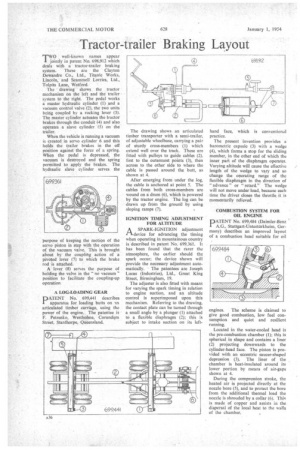
TWO well-known names appear I. jointly in patent No. 698,912 which deals with a tractor-trailer, braking system. These are the Clayton Dewandre Co., Ltd., Titanic Works, Lincoln, and Scammell Lorries, Ltd., To!pits Lane, Watford.
The drawing shows the tractor mechanism on the left and the trailer system to the right. The pedal works a master hydraulic cylinder (1) and a vacuum control valve (2), the two units being coupled by a rocking lever (3). The master cylinder actuates the tractor brakes through the conduit (4) and also operates a slave cylinder (5) on the trailer.
When the vehicle is running a vacuum is created in servo cylinder 6 and this holds the trailer brakes in the off position against the force of a spring. When the pedal is depressed, the vacuum is destroyed and the spring permitted to apply the brakes. The hydraulic slave cylinder serves the purpose of keeping the motion of the servo piston in step with the operation of the vacuum valve. This is brought about by the coupling action of a pivoted lever (7) to which the brake rod is attached.
A lever (8) serves the purpose of holding the valve in the "no vacuum" position to facilitate the coupling-up operation.
A LOG-LOADING GEAR
PATENT No. 699,441 describes apparatus for loading butts on an articulated timber carriage, using the power of the engine. The patentee is • F. Petrenko, Westholme, Corundum Street, Stanthorpe, Queensland.
The drawing shows an articulated timber transporter with a semi-trailer, of adjustable wheelbase, carrying a pair of sturdy cross-members (1) which extend well over the track. These are fitted with pulleys to guide cables (2), first to the outermost points (3), then across to the other side to where the cable is passed around the butt, as shown at 4.
After emerging from under the log, the cable is anchored at point 5. The cables from both cross-members are wound on a drum (6), which is powered by the tractor engine. The lug can be drawn up from the ground by using sloping ramps (7).
IGNITION TIMING ADJUSTMENT FOR ALTITUDE
A SPARK-IGNITION adjustment rt device for advancing the timing when operating in mountainous country is described in patent No. 699,361. It has been found that the rarer the atmosphere, the earlier should the spark occur; the device shown will provide the necessary adjustment automatically. The patentees are Joseph Lucas (Industries), Ltd,, Great King Street, Birmingham, 19.
The adjuster is also fitted with means for varying the spark timing in relation to engine suction, and an altitude control is superimposed upon this mechanism. Referring to the drawing, the contact plate can be turned through a small angle by a plunger (1) attached to a flexible diaphragm (2); this is subject to intake suction on its left
hand face, which is conventional practice.
The present invention provides a barometric capsule (3) with a wedge (4), which forms a stop for the sliding member, in the other end of which the inner pati of the diaphragm operates. Varying altitude will cause the effective length of the wedge to vary and so change the operating range of the flexible diaphragm in the direction of " advance " or "retard." The wedge will not move under load, because each time the driver closes the throttle it is momentarily relieved. .
COMBUSTION SYSTEM FOR OIL ENGINE
PATENT No. 699,484 (Daimler-Benz A.G., Stuttgart-Unterturkheim, Germany) describes an improved layout of a combustion head suitable for oil
engines. The scheme is claimed to give good combustion, low fuel consumption and quiet and resilient running, Located in the water-cooled head is the pre-combustion chamber (1); this is spherical in shape and contains a liner (2) projecting downwards to the cylinder-head face. The piston is provided with an eccentric saucer-shaped depression (3). The liner of the chamber is heat-insulated around its lower portion by means of air-gaps shown at 4.
During the compression stroke, the heated air is projected directly at the nozzle bore (5), and to protect the bore from the additional thermal load the nozzle is shrouded by a collar (6). This is made of copper and assists in the dispersal of the local heat to the walls of the chamber.