


A NEW SYSTEM OF FUEL INJECTION.
Page 46
Page 47
If you've noticed an error in this article please click here to report it so we can fix it.
An Ingenious Device Which, It Is Claimed, Will Allow An Ordinary Engine to Run on Paraffin or Fuel Oil Without Alteration to the Compression Pressure.
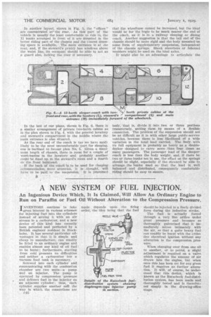
-IINVENTORS continue to take
great interest in various schemes for injecting fuel. into the cylinders instead of mixing it with an air stream in a carburetter, and a new device of this kind has recently been patented and perfected by a British engineer resident in Stockholm. It has several particular advantages in that it is simple and cheap to manufacture,. can -readily be fitted to an ordinary engine and enables almost any kind of oil fuel to be burnt; furthermore, starting from cold presents no difficulties and neither a carburetter nor a vacuum feed tank is necessary.
Screwed into each cylinder and communicating with the combustion chamber are two units---a pump And an injector. The pump is operated by compression pressure and delivers fuel to the' injector on an adjacent cylinder; thus, each cylinder supplies. another ant the way in which the connections are e40 made depends upon the firing order, the idea being that the fuel should be injected in a finely divided form during the induction stroke. • The fuel is actually forced through a very fine orifice under great pressure and becomes so thoroughly pulverized that it immediately mixes intimately with the air, so that a quite heavy fuel can readily be burnt with the erthre (lox electrical ignition without any alteration in the compression pros'sure.
When changing over from one oil to another, or to petrol, a slight adjustment is required on a valve Which regulates the amount of air drawn into the engine, but when once this has been set for any given fuel it requires no further alteration. It will, of course, be understood that this device, which is
• known as the Rutzebeck fuel-distribution system, has been made and thoroughly tested and is therefora not simply in the drawing-office 'stage. Each pump unit consists of a circular casing of about 2 ins, diameter containing a ,corrugated steel diaphragm which is clipped by its periphery between the halves of-the casing. The space below the diaphragm communicates with two pipes through. non-return valves, one leading to the tank and the other to an injector on an adjacent cylinder, as already explained. The pressure of the gases in the corn
bustion chamber deflects the diaphragm and causes it to drive a small quantity of the fuel in the chamber to the injector. When the pressure falls the diaphragm is assisted in returning to its original position by a stiff coil spring and thus draws a fresh charge of fuel from the tank. We understand that the pump action is so efficient that fuel can be raised several feet by this means.
The injector unit consists of a casting screwed into the cylinder which contains an orifice controlled by an adjustable 'needle valve through which the fuel is sprayed. All the needle valves are connected to the accelerator pedal and are provided with fine screw threads; operating the pedal causes the needles to turn through small angles, so opening and closing the orifices simultaneously.