


SOME VARIABLE GEARS.
Page 28
If you've noticed an error in this article please click here to report it so we can fix it.
A Résumé of Recently Published Patents.
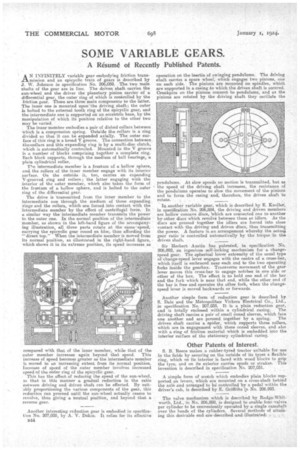
AN INFINITELY variable gear embodying friction transmission and an epicyclic train of gears is described by J. W. Johnson in specification No. 206,059. The two main shafts of the gear are in line. The driven shaft carries the sun-wheel and the driver the planetary pinion carrier of a differential gear, the outer ring of which is controlled by the friction gear. There are three main components to the latter. The inner one is mounted upon'the driving shaft; the outer is bolted to the external tooth ring of the epicyclic gear, and the intermediate one is supported on an eccentric base, by the manipulation of which its position relative to the other two may be varied.
The inner member embodies a pair of dished collars between which is a compression spring. Outside the collars is a ring divided so that it can be expanded axially. The outer surface of this ring is a broad V groove. The connection between theloollars and this expanding ring is by a multi-disc clutch, which is automatically controlled. Mounted in the V groove is a number of blocks comprising together a complete ring. Each block supports, through the medium of ball bearings, a plain cylindrical roller.
'm intermediate member is a frustum of a hollow sphere, and, the rollers of the inner member engage with its interior surface. On the outside it, too, carries an expanding V-grooved ring and rollers ; the latter engaging with the interior of the outer member, which also takes the form of the frustum of a hollow sphere, and is bolted to the outer ring of the differential gear.
The drive is transmitted from the inner member to the intermediate one through the medium of these expanding rings and the rollers, which are forced into contact with the intermediate member by the effect of centrifugal force. In a similar way the intermediate member transmits the power to the outer one. In the normal position of the intermediate member, as shown in the left-hand figure of the accompanying illustration, all three parts rotate at the same speed, carrying the epicyclic gear round en bloc, thus affording the "direct top." When the intermediate member is moved from its normal position, as dilluetrated in the right-hand figure, which shows it in its extreme position, its speed increases as compared with that of the inner member, while that of the outer member increases again 'beyond that speed. This increase of speed becomes greater as the intermediate member is moved to an increasing extent from its normal position. Increase of speed of the outer member involves increased speed of the outer ring of the epicyclic gear.
This has the effect tsf reducing the speed of the sun-wheel, io that in this manner a gradual reduction in the ratio oetween driving and driven shaft can be effected. By suit. ably proportioning the various components of the gear, this reduction can proceed until the sun-wheel actually ceases to revolve, thus giving a neutral position, and beyond that a reverse gear.
Another interesting reduction gear is embodied in specification No. 207,028, by A. V. Dakin. It relies for its effective 134.4 operation on the inertia of swinging pendulums. The driving shaft carries a spare wheel, which engages two pinions, one on each side. The pinions are mounted on spindles, which are supported in a casing to which the driven shaft is secured. Crankpins on the pinions connect to pendulums, and as the pinions are rotated by the driving shaft they oscillate the
pendulums. At slow speeds no motion is transmitted, but as the speed of the driving shaft increases, the resistance of the pendulums operates to slow the movement of the pinions and to force the casing and, therefore, the driven shaft to
rotate. ,
lu another variable gear, which is described by E. Knollef, in specification No. 206,884, the driving and driven members are hollow concave discs, 'which are connected one to another 'by other discs which revolve between them as idlers. As the discs are pressed together the idlers are forced into close contact with the driving and driven discs, thus transmitting the power. A feature is an arrangement whereby the actual gear ratio is controlled automatically by the torque in this driven shaft.
Sir Herbert Austin has patented, in specification No. 206,892, an ingenious self-locking mechanism for a changes speed gear. The spherical lower extremity of the usual type of change-speed lever engages with the centre of a cross-ber, which itself is embraced near each end to the two operating forks inside the gearbox. Transverse movement of the gear lever moves this cross-bar to engage notches in one side or other of the box. The effect is to hold one end of the bar and the fork which is near that end, while the other end of the bar is free and operates the other fork, when the changespeed lever is moved backwards or forwards.
Another simple form of reduction gear is described by S. Dale and the Metropolitan Vickers Electrical Co., Ltd., in specification No. 207,035. It is a plain reduction gear, and is totally enclosed within a cylindrical casing. The driving shaft carries a pair of small coned sleeves, which faCci • one another and are pressed together by a spring. The driven shaft carries a spider, which supports three rollers, which are in engagement with these coned sleeves, and also with a ring of friction material which is embedded into the interior surface of the stationary cylindrical casing.
Other Patents of Interest.
S. B. Reece makes a rubber-tyred tractor suitable for use in the fields by securing on the outside of its tyres a flexible ring, which on its interior is faced with wood blocks to grip the tyre, and on its exterior carries spuds or strakes. This invention is described in specification No. 207,031.
A simple farm of scotch which embodies plain blocks supported on levers, which are mounted on a cross-shaft behind
the axle and arranged to controlled by a pedal within the driver's cab, is described by E. Griffiths in No. 206,993.
The valve mechanism which is described by Rudge-Whitworth, Ltd., in No. 206,898, is designed to enable four valves per cylinder to be conveniently operated by a single camshaft over the heads of the cylinders. Several methods of attaining this desirable end are described and illustratedr