


THE FUTURE OF TI JLTI-WHEEL VEHICLE.
Page 16
Page 17
Page 18
If you've noticed an error in this article please click here to report it so we can fix it.
Six-wheelers Now Commonplace. Possibilitiu ght-wheel, Ten-wheel and Caterpillar Vehicles.
ALTHOUGH THE interesting photographs reproduced in The Commercial Motor some weeks ago showed that six-wheel tractor-lorries were actually constructed so far back as 25 years ago, it is only during the past two years that this type of vehicle has come into its own. On the broadest basis it can now be said that the following types of multi-wheel vehicle have proved practical:—
Six-wheel articulated--(tractor-lorry). Six-wheel rigid—(Goodyear vehicle type). Multi-wheel, separate unit—(tractor and trailer).
Of these varieties the first and third have become very popular, and have shown that remarkably economical results, on a (pay-load) ton-mile-pergallon basis, are a feature of the multi-wheel vehicle. Another very desirable end is achieved by mounting'the load on a large number of wheels—viz., reduced damage to the roads. Ocyneurrently with the trend towards carrying heavier and heavier loads on a single vehicle, we see agitations by highway authorities against any increase of permissible axle weights and speeds, so that an increase in the number of axles appears to be the natural and logical line to take.
A fact which does not seem to be generally recognized is that the vehicle which does the most damage to the roads is the one which itself suffers the most through hammer-blows and shocks transmitted from road wheels to chassis.. Furthermore, the worse the average condition of the road surface becomes the heavier must the chassis be made to withstand ardu ous running conditions. Heavier chassis, again, tend to increased road damage, so that a vicious circle is set up. Then, again, the heavy chaesis ha 8 to be moved by the engine from place to place, and, therefore, entails an increased and needless expenditure of fuel,
The fact that the destructive shocks imparted to a vehicle passing over a rough road are very much reduced in intensity when the load is distributed over six wheels instead of four was conclusively proved by tests carried out two years ago in America. The other important point—economy in running—has been amply demonstrated by the remarkable R.A.C. consumption tests recently described in these pages. There is every reason to suppose that further increases in the number of wheels from six to eight, or even ten, would produce even better results, and here we may cite the remarkable " road-trains" used ,Tava and recently described in these pages.
At first sight one might suppose that a large num, her of wheels and axles, involving more complex steering gear and transmission mechanism, would cause an undue increase in the tare-weight of the vehicle. The writer does not believe that the weight would be increased in this way ; in fact, a reduction might be possible, because two important factors tend to reduce the size and weight of such parts as the frame and axles.
One of these factors is the great reduction in the shocks which the chassis has to withstand when a large number of wheels is used. The other factor is the increase in the number. of points at which the frame is supported. The section and weight of the side-members, for example, depend upon the necessity for providing sufficient stiffness to withstand the load when supported at or near each end. In the multi-wheel vehicle the frame is supported at a number of intermediate points, consequently the bending effect on the frame is reduced and the section of the side-members can be correspondingly decreased. In the same way it is obvious that if a given load is distributed over, sayl four axles instead of two, and the drive is transmitted to two axles instead of one, the dimensions and weight of both the axles and the transmission shafting can be reduced.
Similarly, it is advantageous to distribute braking actions over a large number of wheels. This would present almost insuperable difficulties were a mechanical means of brake-shoe actuation employed, so that with multi-wheel vehicles the pneumatic system is coming into its own. This system confers an additional advantage in that it ensures an equalized pull on all the brakes. A lead in this direction has been given by the Associated Equip- meet Co. in equipping their new tractor-lorry with the Westinghouse system.
The soundness of these contentions is exemplified by railway practice. Here the locomotive axle loads and the number of wheels transmitting the drive must be arranged so as to minimize wear and tear on the track and provide sufficient adhesion for pulling the load. As a result, the weight of large locomotives in this country is distributed over eight or ten wheels, while four or six of these are coupled and transmit the drive. In America the exceptionally long and heavy freight trains necessitate the use of very large locomotives, some of which are equipped with no fewer than 22 wheels! In certain cases the drive is transmitted through 16 wheels arranged on bogies in sets of eight, each bogie carrying a power unit supplied with steam through flexible connections.
Reverting to road vehicles, the comparatively small turning radius required involves difficulties which are not met with in railway practice, so that the analogy of the multi-wheel lorry and the locomotive must not be carried too far. Nevertheless, there are a number of alternative schemes for carrying the load on a larger number of wheels which merit close attention. First, let it be understood that the transport of excoptionally large and heavy weights on one vehicle is the problem under consideration. The fourwheel lorry is, of course, perfectly satisfactory in its own sphere. The question is whether six wheels will eventually prove a sufficient number for loads of 10 tons to 12 tons, and whether vehicles can be developed on these lines capable of carrying 20 tons or more.
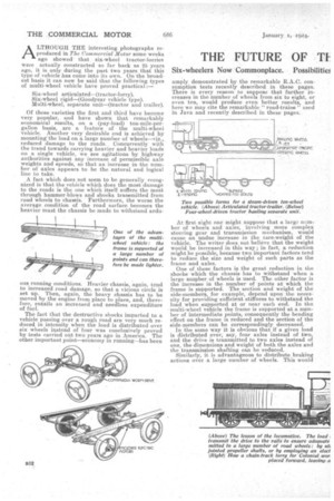
Several alternative conceptions for a rigid petroldriven eight-wheeler are shown in the sketches reproduced. As a development cf the familiar four-wheel type, the rear pair of driving wheels couldsbe duplicated on the lines of the Goodyear design, and the forward part of the chassis supported on four wheels also. These wheels could be mounted on a bogie or placed on pivoted stub-axles linked up to give different degrees of lock. In order to lessen the labour of steering, a system of power operation could be used, sucl. as has been adopted in the case of at least one large American lorry. It would probably be found necessary to allow the rear axles a limited degree of swing when cornering. These axles might be mounted on a pivoted subframe, moving under the control of springs when a corner was negotiated. To lessen the length of the transmission and improve the weight distribution, the engine would be mounted behind the driver's cab. The unloading of a lengthy vehicle from one end presents some difficulties. In another design shown this process could be carried out from the side, and the benefit of a low loading line would be secured. Groups of four wheels support the dropped frame at each end, and the engine and gearbox are mounted at the rear end of the chassis.
Alternatively, in order to secure a handier vehicle, the engine, gearboit and the four driven wheels could be placed near the centre of the frame, and a pair of steering wheels could be mounted at each end. This design would lend itself to the duplication of the driver's cab and controls, so that the vehicle could be driven from either end.
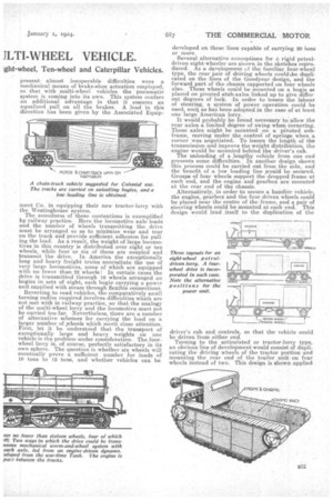
Turning to the articulated or tractor-lorry type, an obvious line of development would consist of duplicating the driving wheels of the tractor portion and mounting the rear end of the trailer unit on four wheels instead of two. This design is shown applied to a steam-driven vehicle with an undertype engine on the tractor.
To improve the steering qualities of the combination it might prove advisable to mount the four trailing wheels on a, bogie, which could be actuated by rods on a system similar to that patented by two concerns for the rearmost axle of a six-wheel tractorlorry.
Apart from the rigid and articulated types, the development of the vehicle designed to tow one or more trailers has considerable possibilities. To obtain sufficient adhesion for towing heavy loads, it is probable that the tractor would have to drive on four wheels. Driving and steering with four wheels is quite a practical proposition, and a central position could be adopted for the power unit with advantage. To assist in manoeuvring the Jonkhoff steering system has great possibilities.
In the case of a steamer, a vertical engine with a unit-constructed gearbox, on the lines of the Yorkshire steam wagon, could be centrally mounted, the drive to the wheels being taken through universally jointed shafts and bevels, as in the case of the remarkable chassis described in these pages a few weeks ago. In order that the vehicle should be controlla,ble by one man, an automatic hopper feed for the boiler would be incorporated.
In any design where more than one axle is to be driven by the engine, the provision of an efficient
transmission is a matter of some difficulty. Each wheel may be driven by a separate shaft, as described above, or a longitudinal transmission shaft carrying worms could be made to drive a number of worm wheels, one being placed at the centre of each axle in the usual way. Perhaps a better solution for the multi-driven-wheel vehicle, especially where the wheels are mounted on swivelling bogies, would consist of driving a dynamo from the engine and incorporating. an electric motor in each axle housing. Flexi
ble wiring connections would permit of the necessary movement between the axles and the frame.
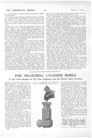
For cross-country Colonial work, where the construction of roads or railways is frequently out of the question for financial reasons, it is essential that vehicles should be developed capable of carrying heavy loads without sinking into soft surfaces. This is pre-eminently the field for the caterpillar or chaintrack, which distributes the load over a large area so that the pressure is only small. Forms of pointed caterpillar track will, no doubt, be developed with a longer life than those common on Tanks during the war. Indeed, a vehicle constructed under the direction of Col. Johnston has already shown that a durable self-lubricating track, free from clogging troubles, is quite a practicable proposition. A special feature of the vehicle to which this track was fitted was that turning could be accomplished without skidding and the concurrent churning up of the soft surface. Actually, soft turf was consolidated and smoothed out by the passage of this vehicle.
The track consists a a number of oval plates, each backed by a hollow steel rib placed centrally. Spherical sockets are formed at the end of each rib, which form bearings for the bolts which join one plate to the next. In this way the track is made extremely flexible and, being under tension, the spherical surfaces become bedded in and exclude dirt and water. The whole track is filled with lubricant when assembled, and can be run for several thousand miles without showing appreciable wear. .
One may surmise that two forms of the caterpillar
load carrying vehicle could be developed. One of these would bear considerable resemblance to the war-time Tank, and, by placing the engine and controls forward, a large loading space would be available between the tracks. Alternatively, in order to secure a larger loading space and a low platform, a dropped frame could be arranged with bogies carrying the engines and caterpillars at each end.