


ASSEMBLING A MOTOR COACH WIRELESS SET.
Page 13
Page 14
If you've noticed an error in this article please click here to report it so we can fix it.
A Design of a Variometer, Together with Some Instructions for 'Making it, are Given in this Issue.
IN THE article of this series in last week's issue of The Commercial Motor, we went into the theory of the variometer, and told how it was employed to make use of the combined effect of the interaction, both magnetic and static, between two coils, in order to provide a smooth and progressive tuning adjustmeat over its whole range. We showed that, owing to the capacity of the arrangement being very small, the inductance to tune to any given wave-length must necessarily be relatively large, and, itherefore, the voltage of signals would also be large, which would result in high efficiency. And we pointed out that
this last consideration, coupled with the fact that the variometer is very compact—seeing that it combines the dual functions of tuning inductance and tuning condenser—was the one that had led us to adopt a variombter as.a means of tuning the aerial on The Commercial Motor set.
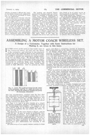
In Figs. 4, 5, and 6 we give details of a simple cylindrical variorneter, which is suitable for covering the broadcasting wave-lengths. It consists of an outer former (Fig. 4), an inner former (Fig. 5); the two being assembled, the one within the other, as shown in Fig. 6.
The diameter of the outer former is 3i ins., and its length 2i ins. It may be made of cardboard tube, or (preferably) of ebonite. If of cardboard, the tube must be well impregnated with paraffin wax in order to render its insulation sufficiently good. As this is art operation that is frequently in demand in the construction of radio apparatus, it is fitting that we should here give instructions for carrying it out properly.
All substances of an organic nature contain in their
pores and fibres a surprising amount of moisture. This is partially due to the natural moisture inherent in all things which grow, and partially to the capacity of such substances for absorbing moisture from the atmosphere. Now, as is well known, water is a very bad insulator from an electrical point of view ; in fact, it is a very good conductor of electricity, so that, if we have a substance which containa in its pores a large amount of moisture, we shall not be able to expect very high insulation properties from it. It is no use drying such a substance in an oven, because, although this procedure would drive off the moisture, the substahce would quickly absorb a fresh quantity from the air, and so we should be as far off as ever.
What we need is to stop up the pores of the substance with some insulating compound that is in itself impervious to moisture. Nothing is better for our purpose than paraffin wax, which is the solid white wax-like substance from which candles are made. Not only is paraffin wax quite waterproof, but it is also one of the finest insulators known to sciencet and the fact that its boiling-point is very much higher than that of water allows us easily to get rid of this undesirable element.
To treat cardboard, or wooden formers and such articles, proceed as follows :—Into an old iron saucepan of sufficient size to contain the articles to be treated put enough candles to fill, when melted, the saucepan three-parts full. Set over a very small fire—a gas-ring turned down low is best—and allow to melt. When completely melted, remove the wicks and allow the temperature to rise until a small piece of wood dipped into the wax just starts to turn brown. Then drop in the articles to be treated. It will be found that this will be accompanied by a great evolution of bubbles, which are due to the moisture in the substance being evaporated. When all the bubbling has finished, turn off the gas or take the saucepan off the fire, and allow the wax to cool down (with the former or other article still in it) until it is just on the point of solidifying. Then take out and drain, and,
)V-7.
ISS MOO
Fig. 6,— Mnznting the rotor in the stator by means of screwed spind:es, to one of which is attached the knob for varying the relative positions of the twc
parts. whilst still warm, wipe off the surplus wax. This procedure, if carefully followed, will result in apparatus of as high an insulating quality as ebonite at a fraction of the cost.
To return to the variometer. The inner former is ins, in diameter and 1 ins, long, and must like wise be treated in paraffin wax. When both formers are prepared they should be wound as follows :—The outer former with 45 turns of No. 26 double cottoncovered wire, the inner with 55 turns, also of No. 28 double cotton-covered wire.
The winding on the outer former should commence, at about +, in. from one end2 the method of securing the wire being that shown in Fig. 7. Simply make two holes in the former about in. apart, and thread the wire down through one hole and back up through the other one. Wind on 22 turns close together, then take one turn across, leaving a gap of about f,
after which a further 22 turns should be wound on and the end of the wire secured, as shown on Fig. 8.
The inner former should be treated in the same way, the winding starting in. from the cud of the former, 27 turns being wound, then a gap of in., after which a further 27 turns,
Fig, 6 shows clearly the method of assembling the variometer. Two short pieces of No. 4 B.A. screwed brass rod are securedtoeach side of the rotor by nuts. One of these carries the operating knob as shown. The rods pass through holes in the stator. The two ends of the rotor winding are fastened, each to one of the spindles: One end of the stator winding is also connected to one of the spindles. This leaves the other end free to be connected to the aerial terminal, whilst the wire from the other spindle is connected to the earth terminal. The connections are shown in Fig. 7. It will be seen that the stator and rotor are connected in series between the aerial and the earth.