


FINE ENGINE: HELPFUL KI
Page 104
Page 105
Page 106
If you've noticed an error in this article please click here to report it so we can fix it.
Overhauling an engine can be a daunting and frustrating task: Running around getting the parts you need when you need them interrupts an involved and complicated job. Gardner has introduced kits containing all the necessary parts to rebuild its engines. Colin Sowman went to the company's plant to see what is involved in a top end overhaul
THE GARDNER engine has beautifully machined, matched and balanced component parts. It is an engineer's engine. If, for instance, one lobe gets damaged on the camshaft, then only that pair of cams needs changing — not the entire shaft.
This type of construction can make a total strip-down complicated, but in most cases a major repair can be carried out without stripping the engine into its component parts, and many overhauls finished with the engine still in the chassis. If both the top and bottom ends need attention, (remembering that Gardners have to be turned upside down to install the crank) it is probably more cost effective to get a factory reconditioned exchange unit.
For those wishing to do their own overhauls, Gardner markets a range of kits containing all the necessary parts and gaskets. Workshop went along to Patricroft to see what was involved in a top-end overhaul of a 236kW (310hp) 6LXDT using the Gardner kit.
The complete top-end overhaul undertaken will mean replacing the cylinder block, pistons, big ends and heads. A kit (Part No A07118) containing all these parts along with the necessary gaskets and filters costs 11,636.21 (excluding VAT) from Gardner distributors. While it is normal for this type of overhaul to be carried out in the chassis, the engine we watched being worked on was out of the vehicle for photographic purposes.
Start these tasks
Start with the obvious items like draining the oil, removing the alternator and disconnecting the fuel feed to the injection pump. Unlike many engines, the Gardner has external water rails mounted above and below the manifolds. The turbocharger oil feed must be disconnected; this comes directly from the top of the oil filter situated at the rear nearside of the engine. The oil-pressure relief valve is also in this area. This is a spring-loaded, plunger-type device and should not be tampered with in an attempt to boost oil pressure because the bypass lubricates the timing chains and these could run dry if the setting is disturbed. Next remove the compressor. All the external pipes on the engine can now be removed complete with the oil filter housing.
It is now possible to remove the top and bottom water rails. Note at this point that while the cylinder heads are identical, the studs securing the top water rail are longer on the front one than the rear. The water pump was also removed at this point (although it is not required for this job), to illustrate the drive arrangement.
A square shank transmits the drive to the pump via a waisted shaft. If an object gets into the pump, the shaft will shear at the waisted section to prevent hither damage. Should there be an overheating problem with a Gardner, first check this drive shaft. Do not remove the plate into which the pump locates because there are no seals to prevent the oil from leaking out and the setting for the retaining system will be distroyed if taken off. This plate must remain with its engine at all times; do not be tempted to fit it to any other engine.
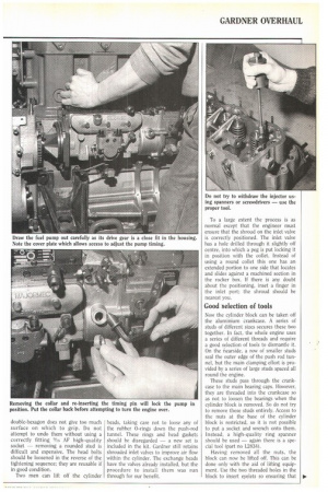
Rotate the engine While it was not required for our stipdown, the injection pump was also removed to demonstrate the procedure. First rotate the engine until number one cylinder is starting its injection period — there is a mark on the flywheel and an inspection cover on the bell housing. Take out the pump timing pin (directly below the rack) with a hexagonal wrench, remove the collar and screw the pin in to its full depth. This will lock the pump with the timing in the correct position.
Check that all the oil pipes have been removed from below the injection pump and undo the four bolts holding it to the chain case and the bracket at the rear. The pump can now be drawn out. Its drive gear is a tight fit in the chain case and must align fully before removal is possible.
Next remove the rocker covers. The short injector pipes can be removed by undoing the union and the single bolt that holds each cover plate to the head. Disconnect the spill pipes from the injectors. However, there is no need to remove them entirely. There are three studs holding each injector in — remove the nuts from them. Do not attempt to get the injectors out by using spanners or screwdrivers since this will only cause damage to them and the heads; use a proper tool like the one shown opposite or service tool number L28696.
The push rods are removed next. To do this, select the cylinders at the top of their stroke, compress the vlalves (again a tool is available but most fitters know dodges to do this) and take the rods out of the rocker cups. Turn the engine so that the next two cylinders are around TDC and repeat the process until all the push rods are disengaged. If the same heads are to be put back it is best to mark the rods so that they go back in the same place. As we were going to fit different heads this did not matter.
Double-hexagon (12 pointed) headed studs secure the heads to the cylinder block. These are very tight and the
double-hexagon does not give too much surface on which to grip. Do not attempt to undo them without using a correctly fitting 9/15 AF high-quality
socket removing a rounded stud is difficult and expensive. The head bolts should be loosened in the reverse of the tightening sequence; they are reusable if in good condition.
Two men can lift off the cylinder heads, taking care not to loose any of the rubber 0-rings down the push-rod tunnel. These rings and head gaskets should be disregarded — a new set is included in the kit. Gardner still retains shrouded inlet valves to improve air flow within the cylinder. The exchange heads have the valves already installed, but the procedure to install them was run through for our benefit.
To a large extent the process is as normal except that the engineer must ensure that the shroud on the inlet valve is correctly positioned. The inlet valve has a hole drilled through it slightly off centre, into which a peg is put locking it in position with the collet. Instead of using a round collet this one has an extended portion to one side that locates and slides against a machined section in the rocker box. If there is any doubt about the positioning, inset a finger in the inlet port: the shroud should be nearest you.
Good selection of tools
Now the cylinder block can be Laken off the aluminium crankcase, A series of studs of different sizes secures these two together. In fact, the whole engine uses a series of different threads and require a good selection of tools to dismantle it. On the nearside, a row of smaller studs seal the outer edge of the push rod tunnel, but the main clamping effort is provided by a series of large studs spaced all round the engine.
These studs pass through the crankcase to the main bearing caps. However, they are threaded into the crankcase so as not to loosen the bearings when the cylinder block is removed. So do not try to remove these studs entirely. Access to the nuts at the base of the cylinder block is restricted, so it is not possible to put a socket and wrench onto them. Instead, a high-quality ring spanner should be used — again there is a special tool (part no L2834).
Having removed all the nuts, the block can now be lifted off. This can be done only with the aid of lifting equipment. Use the two threaded holes in the block to insert eyelets so ensuring that
41 the lift is as parallel as possible. Turning
the engine so that the two centre pistons are at the top of their stroke will ease the effects of a non-parallel lift and is a good precaution. If there is a spacer shim underneath the block, remove and disguard it.
Next remove the sump pan from the bottom of the crankcase. The big end and main bearings are then exposed. Remove all the big-end bearing caps (four bolts in each), and take the pistons complete with con rods out from the top of the crankcase. All Gardner con rods are matched to their caps and marked with the cylinder number. Note that all markings of pistons, con rods and caps are on the tappet side.
The new block can now be placed onto the crankcase. If a spacing shim is required with the particular block, a plate giving the thickness will be riveted to the casting and it will be included in the kit. Where no spacer is required there is no plate on the block. A sealing compound is required on the block to crankcase joint and should be applied above and below the shim, if fitted. Hilosit is recommended for this and other joints on the 6EXTD.
Now the cylinder block can be lowered onto the crankcase (with the shim in between if required) locating on the studs. When securing the block, start with the large studs in the centre and work outwards tightening opposite side nuts evenly and in sequence until a torque of 186Nm (137 lbft) is reached. There is no torque setting for the smaller nuts around the push-rod tunnel.
To remove the pistons from the con rods, Gardner produces a special tool (part no 01074). When fitting the new pistons ensure that all the markings are on one side and that each ring's gap is at 180° to the one above and/or below. Each piston can now be inserted into its respective cylinder by using a ring clamp. Check that all the markings are towards the tappet side of the engine.
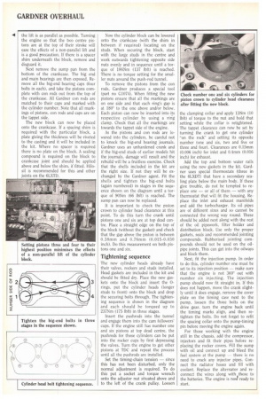
As the pistons and con rods are lowered into the cylinders, be careful not to knock the big-end bearing journals. Gardner uses an unhardened crank and if the big-end studs of earlier models hit the journals, damage will result and the rebuild will be a fruitless exercise. Check that the shells included in the kit are the right size. If not they will be exchanged by the Gardner agent. Fit the shells and tighten the big-end bolts (again numbered) in stages in the sequence shown on the diagram until a torque of 90Nm (66 lbft) is reached. The sump pan can now be replaced.
It is important to check the piston crown to cylinder head clearance at this point. To do this turn the crank until pistons one and six are at top dead centre. Place a straight edge on the top of the block (without the gasket) and check that the gap above the piston is between 0.38mm and 0.76mm (0.015-0.030 inch). Do this measurement on both pistons one and six.
Tightening sequence
The new cylinder heads already have their valves, rockers and studs installed. Head gaskets are included in the kit and should be fitted dry. Place the new gaskets onto the block and insert the 0rings, put the cylinder heads (longer studs to front) onto the block and drop the securing bolts through. The tightening sequence is shown in the diagram and each should be torqued up to 237Nm (175 lbft) in three stages.
Insert the pushrods into the tunnel and engage them into the cam followers' cups. If the engine still has number one and six pistons at top dead centre, the pushrods for those cylinders can be put into the rocker cups by first depressing the valves. Turn the engine to get other pistons at TDC and repeat the process until all the pushrods are installed.
Set the timing-chain tension — since this has not been disturbed, only the normal adjustment is required. To do this put a socket and torque wrench onto the adjuster nut situated above and to the left of the crank pulley. Loosen the clamping collar and apply 13Nm (10 lbft) of torque to the nut and hold that setting while the collar is retightened. The tappet clearance can now be set by turning the crank to get one cylinder "on the rock" and setting its opposite number (one and six, two and five or three and four). Clearances are 0.15mm (0.006 inch) for inlet and 0.4rnm (0.016 inch) for exhaust.
Add the top and bottom water rails using the new gaskets in the kit. Gardner uses special thermostats (three in the 6LXDT) that have a secondary sealing plate below the main body. If these give trouble, do not be tempted to replace one — or all of them — with any thermostat that will fit the housing. Replace the inlet and exhaust manifolds and add the turbocharger. Its oil pipes are of different sizes and so cannot be connected the wrong way round. These should be added next along with the rest of the oil pipework, filter holder and distribution block. Use only the proper gaskets, seals and recommended jointing compounds. Rubberised jointing compounds should not be used on the oilpipe joints. This can get into the oilways and block them.
Next, fit the injection pump. In order to do this, cylinder number one must be set to its injection position — make sure that the engine is not 360° out with number six injecting. The injection pump should now fit straight in. If this does not happen, move the crank slightly until it does engage, remove the cover plate on the timing case next to the pump, loosen the three bolts on the drive gear, turn the engine back until the timing marks align, and then retighten the bolts. Do not forget to refit the spacing collar onto the pump-timing pin before moving the engine again.
For those working with the engine still in the chassis, add the compressor, injectors and fit their pipes before replacing the rocker covers. Fill the sump with oil and connect up and bleed the fuel system at the pump — there is no need to crack any injector pipes. Connect the radiator hoses and fill with coolant. Replace the alternator and reconnect the wires along with those to the batteries. The engine is now! ready to start.