


OVERHAULING THE ORWELL ELECTRIC.
Page 27
Page 28
Page 29
If you've noticed an error in this article please click here to report it so we can fix it.
No. 8.—The Orwell—What Should Be and What Should Not Be Tackled. Testing Electrical Connections. Adjusting and Repairing the Controller and Motors. Accumulators and Their Troubles.
THE AVERAGE repairer is somewhat chary of tackling the electric vehicle. He looks upon it with a certain amount a awe as being a mystery to him as regards much of its mechanism. Why this is so is difficult to understand, as the electric 'vehicle is certainly one of the most simple to maintain and to repair. The electrical knowledge required for the latter need be very slight, and is chiefly a matter of the use of common sense.
Taking everything into consideration, there are only two components of the electrical vehicle which must he treated with the utmost respecE, and which it is preferable to refer to experts in the one case and to the makers in the other if the repairs required are extensive; these are the armatures of the motors and the accumulators Even repairs to armatures can be successfully dealt with up to a certain point, but rewinding should not be attempted except by an expert.
The batteries are usually guaranteed by the makers, and one of the conditions ot the guarantee is that the batteries shall not be interfered with except for cleaning and filling with distilled water when required; even acid may not be added without the written permission of the battery makers, but we shall have more to say on this subject later on in the article.
For testing the electrical connections, the use of an instrument called the Megger, and manufactured: by Evershed and Vignoles, Ltd., Acton Lane Works, Chiswick, London, W., and others, is almost essential if a number of electrically-driven vehicles is being dealt with. The price -of this instrument is 232 liz. id. for the smaller size, and 234 4s. 6d. for the larger size.
The overhauling of an electric vehicle differs in many respects from the overhauling of a petrol chassis. In the latter a. considerable portion of the work consists of dismantling units, and hints are often required in order that this shall be done expeditiously and with the minimum_ of labour. In the electric vehicle there are remarkably few parts to dismantle and much of the work can be done whilst the units or their castings are left in. situ. This, of course, applies to the electrical parts of the machine, the mechanical details, such as wheels, springs, brakes, etc., can be dealt with. in exactly the same naanner as those on a petrol Vehicle, except in so far as the
particular machine is concerned. Many of the hints apply just as much to ordinary maintenance as to actual overhauling, but it is important that they should be included.
Testing for Electrical Faults.
Perhaps the most important item in the work of ' repairing an electrical vehicle is to make certain that the electrical connections are perfect and that there are no leakages in the various circuits. One of our illustrations shows the Megger in use. The battery must be disconnected from the controller before testing with it. It consists of an ohmmeter of the moving coil type, combined in one box with a hand-driven dynamo which provides current for the tests. Two wires lead from it, one being connected to earth (in other words, some part of the chassis frame), whilst the other is held by the tester and brought into contact in turn with the various parts to be tested.; another man drives the generator and watches the painter of the ohmmeter. If there are no leakages in the, circuit under test,the electrical resistance is shown to be very high, whilst any losses and a comparison of the total amounts lost are shown by a reduction in the resistance registered. Directly it is determined that. any leakage has occurred, the cause can be traced out in that particular circuit and may prove something quite easy to repair or replace, such as a chafed wire.
Adjusting and Repairing the Controller.
Great care should be exercised in properly adjusting the main controller. The segments should be examined for wear and replaced if necessary, and the contact fingers must exercise even pressure on the segments. Each finger can be adjusted by undoing the one nut locking it and moving it backwards or forwards as is required, for which purpose it is slotted where held on its stud. The roller of each finger should be in contact with its segments over its whole width. The inter-locking pins and the cut-out con
trolling mechanism must also be examined for wear and, adjusted where necessary. After repair, the segments should be lightly smeared with vaseline, as this keeps them in good condition and prevents burning. Incidentally, it is necessary that this should be done, periodically whilst the vehicle IS in service. A simi
lax procedure is followed with the controller switch gear used with the Orwell tipping gear, which is Operatediby a separate motor.
• Attending to the Motors.
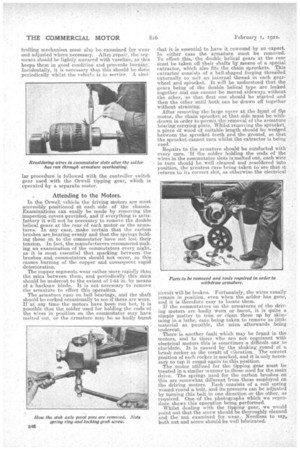
In the Orwell vehicle the driving motors are most accessibly positiOned at each side of the chassis. Examinations can easily be made by removing the inspection covers provided, and if everything is satisfaCtory it will not be necessary to remove the double helical gears at the rear of each motor or the armatures. In any case, make certain that the carbon brushes are bearing evenly and that the springs holding these on to the commutator have not lost their tension. In fact, the manufacturers recommend niaking an examination of the commutators every night, as it is most essential that sparking between the brushes and commutators should not occur, as this causes burning of the copper and consequent rapid deterioration.
The copper segments wear rather more rapidly than the .mica between them, and periodically this mica should be undercut to the extent of 1-0.4 in. by means of a hacksaw blade. It is not necessary to remove the armature to effect this operation. The armature runs on ball bearings, and the shaft should be rocked occasionally to see if these are worn. If at arty time the motors have been run hot, it is possible that the solder used for holding the ends of the wires in position on the commutator may have melted out, or the armature may be so badly burnt
that it is essential to have it rewound by an expert. In either case the armature must be removed. Th effect this, the double helical gears at the rear must be taken off their shafts by means of a special extractor, which also fits the chain sprockets. This extractor consists of a bell-shaped -forging threaded externally to suit an -internal thread in each gearwheel and sprocket. It will be understood that the gears being of the double helical type are locked together and one cannot be moved sideways without the other, so that first one should be started and then the other until both can be drawn off together without straining.
After removing the large cover at the funi of the motor, the chain sprocket at that side must be withdrawn in order to permit the removal of thearmature bearing carrying plate. Whilst removing the sprocket, a piece of wood of suitable length should be wedged between the sprocket teeth and the ground, so that the sprocket cannot turn whilst the extractor is being used.
Repairs to the armature should be conducted with every care. 'If the solder holding the ends of the wires in the commutator slots is melted out, each wire in turn should be well cleaned and resoldered into position, the greatest care being taken to see that it retarns to its correct skit, as otherwise the electrical circuit will be broken. Fortunately, the wires usually remain in position, even When the solder has gone, and it is therefore easy to locate them.
If the commutators on the armatures of the driving motors. are badly worn or burnt, it is quite a• simple matter to true or clean • these up by skimming in a lathe, care being taken to remove as little material as possible, the mica, afterwards being undercut.
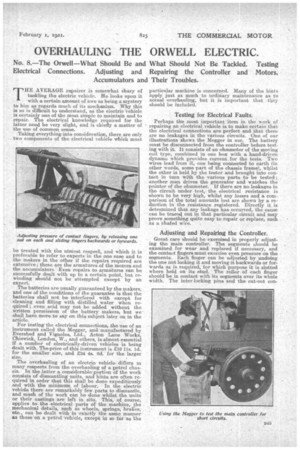
There is another fault which may be found in the • motors, and to those who are not cognizant with electrical motors this is sometimes a difficult one to elucidate. It is caused by the shaking round of a brush rocker as the result of vibration. The correct position of each rocker is marked, and it is only necessary to tap it round again to this position. The motor utilized for the tipping gear must be treated in a similar manner to those used for the main drive. The springs used for the carbon brushes on this are somewhat different from those employed on the driving motors. Each consists of a coil spring wound round a bolt, and its pressure can be adjusted by turning this bolt in one direction or the other, as required. One of the photographs which we reprodude shows this operation being performed. Whilst dealing with the tipping gear, we would point out that the screw should be thoroughly cleaned and the nut examined for wear. Needless to say, both nut and screw should be well lubricated. For removing the wheels, a special extractor, provided as standard equipment with each chassis, must be utilized. This extractor, which is shown in one of our illustrations, is screwed into position in place of the hub cap, and by turning the long centre screw the wheel can be withdrawn with the utmost ease, although, of course, before doing so, the split-pinned nut mu.st be taken off. Each nut bears a number which corresponds with one on the axle; when this number registers exactly, the adjustment should be correct, but if wear occurs the nut can be taken pp a. little more, in which case the new position should be marked in a similar manner.
The bearings employed on the rear wheels are Timken taper roller. On the older models Timken bearings were also employed on the front wheels, but on the later types Skefkcr are employed. With the latter, the nut can be drawn up tight, but with the Timken care must be exercised not to put undue pressure on the rollers.
At the inner side of each rear wheel is a thick felt washer to prevent leakage of oil. If these washers are badly worn, they should be replaced. It may sometimes be necessary to remove the stub axle pivot pins. Each pin is locked into the axle by means of a. grub screw, which is always at the front and is recessed back into the axle. The ball bearing at the top of the pin iS held in position by a spring ring, which can be removed by gripping the two ends together between the jaws of a pair of pliers. The pin can then be drifted out front the bottom. When replacing it, it can be hammered into the aide as far as it will go, as it butts up against a shoulder. When in position, care must be taken to replace the spring ring and locking grub screw.
Steering Gear.
The steering gear is conveniently situated right at the front of the frame. It is of excellent design, and is provided with two means of adjustment—one for ' the ball thrust bearing of the worm and the other far altering the centres of the worm, and, segment, thus taking up backlash. The adjustment for the front bearing is afforded by a slotted nut carried at the bottom of the steering box and locked in position by a. plate. To effect adjustment, this plate must be released, when the nut can be turned pne or more slots as required, and the plate replaced. The steering segment is supported in eccentric bushes. Round the flange of each are spaced recesses into one of which fits a, locking set-screw supported in a small bracket secured to the steering. box. Each bush can be turned round to the required position after releasing the set-screw, which must, of course, be tightened up after the adjustment is effected. There are two internal-expanding brakes operated by self-adjusting sliding cams. The shoes are covered with woven asbestos fabric riveted in position, and this fabric may require renewing. The ad
justment of the brakes is by large sleeve nuts on the operating rods, and it is of interest to note that the tension of the pull-off springs is not altered when adjustments are made, as each spring is anchored to the rod ahove the points where adjustments are effected.
Care of Accumulators.
The batteries which are used in the Orwell electric are manufactured by the Chloride Electrical Storage Co., of Clifton Junction, near Manchester, and for the convenience of repairers and others dealing with batteries of this make, the company issue a most useful booklet, which gives details of the care which should be taken of batteries from the time they are yeceived. It also gives useful instructions regarding charging and such repairs as the company recommend as being suitable for carrying out by others than themselves.
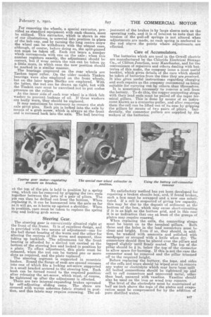
It is sometimes necessary to remove a cell from the battery. To do this, the copper connecting straps With their lead ends must be pulled off the taper terminal pillars. This is done by means of an in.strumerit known as a connector puller, and after removing them the cell can be lifted out of its case by gripping the pillars by means of two pairs of pliers. Incidentally., the connector pullers ale supplied by the makers of the•batteries. • No satisfactory raethod has yet been developed for repairing a broken ebonite box, and, if found broken, such a. box must be scrapped and a new one substituted. If a cell is suspected of giving low capacity, this may be due to the deposit of sediment at the bottom of the box' which may cause short-circuiting if it is as high as the bottom grid, and in this case it is an indication that one at least of the groups of plates may require renewal.
When replacing the cells, the connecting straps must be burnt on to the terminal pillars. Both these and the holes in the lead connectors must be clean and bright. Even if so, they should, in addi tion, be washed with ammonia and polished with sandpaper or scraped with a knife when dry. The connectors should then be placed over the pillars and tapped slightly until firmly seated. The top of the pillar should be * in. below the top of the connector to allow space for burning. If this is not the case the connector must be removed and the pillar trimmed off to the required height.
Before replacing the battery, the tops, and sides of the cells and trays should be wiped over to remove any water or electrolyte which may have been spilt All bolted connections should be tightened up and cell to cell connectors and uncovered metal, other than lead, smeared with vaseline. Vaseline should also be used on the iron or wood tray runners. The level of the electrolyte must be maintained at half an inch above the tops of the plates and evaporation must be compensated for by the addition of pure distilled water.