


With Intent to Improve.
Page 24
If you've noticed an error in this article please click here to report it so we can fix it.
A Weekly Summary of Recent Patents, of Interest to the Maker and User of Commercial Motor Vehicles.
Selected and Abridged by H. S. Hall, A.M.I.A.E.
In Lieu of a Split Pin.
In engineering construction it is of ten the apparently simple that somehow proves the most difficult of practical attainment. Just such a case is the coupling of small oontrol rods to their respective levers. The most mechanical method of doing this, and the one which, considered from an engineering standpoint only, is the best, is that employing a small jaw aid on the end of the coupling rod, holed for a suitable pin, which is, when in place, secured by a washer and split pin. In the alternative, where a certain amount of movemeirt of the rod in two planes is anticipated, shall -joint is usually fitted. The objection to the first-named is its expense; to the second, that the majority of ball joints, naturally subject to wear, soon become liable to detachment. A common but not satisfactory way of proceeding is to bend the end of the control rod and bore a hole in the lever of a size suitable for receiving it. That portion of the rod which protrudes is drilled and a split pin fitted. To the engineering mind, such a proceeding is an abhorrence.
The paters, No. 100,007, by C. S. Felton, of Chatfield ' _Drive, Cleveland Heights, Ohio, U.S.A., is an attempt to improve the last-named method. Reference to our illustration will make it clear that a clip of suitable, soft material is _ designed so that it can be engaged with that portion of the rod adjacent to the lever, while the bored end of it surrounds the projecting piece of coupling rod; so placed, it will be evident that the control rod is satisfactorily secured in position, and the need for drilling and fitting of a split pin is obviated.
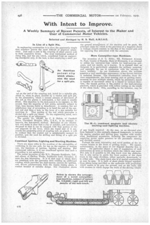
Combined Ignition, Lighting.and Starting Machine.
There are many sides to the question of the advisability of combining in the one unit, for use on the engines of touring cars, the functions of ignition, lighting and starting. For commercial vehicles, it is our considered opinion that such a proceeding is not satisfactory. The recent invention of the M.L. Magneto Syndicate, Ltd., and others, of Oarlton Works, Lockhurst Lane, Coventry, is none the less interesting. It is of that type in which there are combined ith the generator field winding an additional winding which provides the high-tension current for ignition, and, driven synchronously from the engine timing gears, a contact breaker of suitable design. Our illustration shows the general arrangement of the machine and its parts, the principal claim for which is the provision of a magnetic shunt or leakage circuit common to the flux of the wound pole and the opposing flux associated with the armature.
More Caterpillar-type Machines.
The invention of S. G. Miller, 703, Fairmount Avenue, St.. Paul, County of Ramsey, State of Minnesota, is an attempt to utilize the caterphar-type vehicle fur load-carrying purposes, and not merely as a tractor. It is claimed that, as designed, it is particularly adaptable for military purposes, and especially for use in connection with the carriage of
heavy artillery. As our illustration shows, the machine presents a very unorthodox appearance; it has several features of technical interest. The construction embodies three distinct compartments, the front steering unit or guiding frame, mounted on four multiple wheels, which by pneumatic means is capable of movement either in a lateral or vertical direction; the second portion is the,central or the load-carrying platform, Nihich is provided with rollers resting on the inside of the chain track. This, according to the inventor, may be of any length required. At the rear, on an elevated platform fastened to this centrally-disposed framework, is carried the engine, gearbox and driving gear, together with sundry other mechanical accessories, including the compressor for supplying power under pressure to the pneumatic steering and elevated control.
Perhaps the most interesting and novel portion of the invention relates to the front or guiding truck. We cannot, unfortunately, in the space at our disposal describe this in detail. Its particular object is ease of negotiation of such obstructions as trees or boulders which the vehicle may meet. Not only is it possible to lift this truck over the obsfacles, but it also serves to guide the front portion of the chain track in the right direction, either upwards, downwards or to either side. The chain track also is of special construotion; as may be seen. It is built of short, plates hinged together, these plates being provided on the underside with projections which enable it to grip the ground, and on the inner. side with recesses in which engage the teeth of the driving wheels: