


German After-the-War Preparation.
Page 14
Page 16
Page 17
If you've noticed an error in this article please click here to report it so we can fix it.
A Dutch Journal Commences a New Feature, Dealing with Commercial Motorism, by a Description of the Adler Chassis.
A now departure of considerable importance at the present juncture is to be noted in the policy of the Dutch journal, the "Auto-Leven." This periodical generally confines, its attention to matters affecting motorcycles and touring cars ; references to commercial. vehicles have hitherto been few and far between. hi the issue of the 20th ultimo, however, what is evidently intended to, be in the near future a regular featuic commences under. the heading "Commercial Motorism."
A Sign of German After-the-War Preparations.
It is significant that the first vehicle to be dealt with at any length is the German-constructed Adler. That there can be little in the way of intention behind this publicity, which has evidently been sought by the German manufacturers, except after-the-war propaganda, we are sure. If proof were wanted that this was the case, it is afforded in the opening paragraph of the artide to which we refer, in which for the benefit of readers it is made patently plain that orders for these chassis must not be taken if immediate delivery is regarded as a sine Qua non, the fact of the matter being that the German military authorities are still taking the full output of the works. Before the -war the Adler Co. were engaged upon the construction of light vans and touring cars, as well as in the manufacture of heavy vehicles such as those described. At present, however, the output is to all intents and purposes limited to that of commercial wagons suitable for loads of from two to five tons. Although it is not at all likely that any of our readers will find the following description of direct use, inasmuch as there are none likely to be purchasing a machine of this or any oilier German company's manufacture for a long time to come, a description with the drawings accompanying it may be of interest to our own British manufacturers.
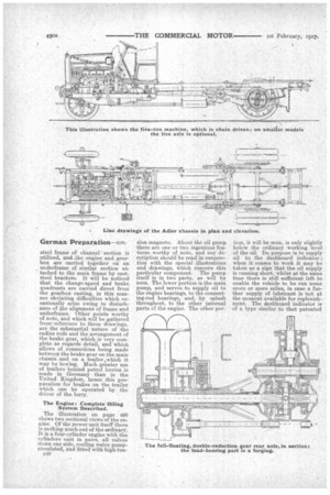
For Loads of Two to Five Tons, Chain or-Gear Drive.
As stated, the chassis are made for loads of from two to five tons, and in various models. In general design they are similar. Concern ing those for loads of 3i tons am under, alternative methods of thaa drive . transmission are offered either by roller chain or by liv, axle. On chassis for loads of ove 31 tons the chain-drive type only i made. It is of interest here t4 note that the German military au thorities favour chain transmissim rather than any other for -heavy ye hicks. This contrasts with the at titude adopted by our dwn Wa Office. Again, on those chassis fo loads of 31 tons and under, a choici of two sizes of engine is offered either 103 mm. by 135 mm. bore am stroke, developing 25 h.p., or 11( mm. by 140 min., developing 35 h.p On the heavier vehicles, 40 h.p. en gines of 114 mm. by 160 mm. bon and stroke arc standardized. It 1; interesting to note the stroke-bon ratio, which, in the sizes given averages 1.32 with a maximum o. 1.4.
Outstanding Features.
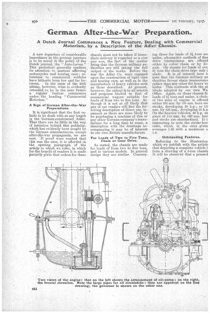
Referring to the illustration which we publish with the article that depicting a complete vehicle i from a drawing of a, 5-ton chassis It will be observed that a pressed
steel frame of channel section is utilized, and the engine and gearbox are carried together on an underframe of similar section at-. tached to the main frame by caststeel brackets. It will be noticed that the change-speed and brake quadrants are carried direct from the gearbox casting, in this manner obviating difficulties which occasionally arise owing to disturbance of the alignment of frame and underfraine. Other points worthy of note, and which will be gathered from reference to these drawings, are the substantial nature of the radius rods and the arrangement of the brake gear, which is very complete as regards detail, and which allows of connections being made between the brake gear on the main chassis and on a trailer ,which it may be towing. Much greater use of trailers behind petrol lorries is made in Germany than in the United Kingdom, hence this preparation for brakes on the trailer which can be operated by the driver of the lorry.
The Engine: Complete Oiling System Described.
The illustration on page 490 shows two sectional views of the en gine. Of the power unit itself thereis nothing much out of the ordinary. It is a four-cylinder engine with the cylinders cast in pairs, all valves down one side, cooling water pumpcirculated, and fitted with high-ten C46 sion magneto. About the oil pump there are one or two ingenious features worthy of note, and our description should be read in conjunction with the special illustrations and drawings, which concern this particular component. The pump itself is in two parts, as will be seen. The lower portion is the main pump, and serves to. supply oil to the engine bearings, to the connecting-rod bearings, and, by splash throughout, to the other internal parts of the engine. The other por tion, it will be seen, is only slightly below the ordinary working level of the oil. Its purpose is to supply oil to the dashboard indicator ; when it ceases to work it may be taken as a sign that the oil supply is running short, whilst at the same time there is still sufficient left to enable the vehicle to be run some score or more miles, in case a further supply of lubricant is not at the moment available for replenishment. The dashboard indicator is of a type similar to that patented in this country by Benton and Stone, and known as the Enots. In the ordinary course of events the small upper pump drives /oil up to this indicator. The oil pours out of the little pipe within the glass dome, and returns via another pipe to the crankcase. So far there is nothing new. Attention, however, is directed to the third pipe in the centre. This pipe connects the dashboard indicator to the cardan shaft joints On the live-axle machine ; by pressing a small lever, shown at the right of our illustration, the delivery pipe from the small upper pump is placed in direct communication with the central pipe, and instead of oil being pumped through the indicator, it is pumped direct to the universal joints on the propeller shaft. This proceeds only so long as the driver's hand is pressing the small lever aforesaid ; as soon as his hand is removed, the lever is returned by the pressure of a spring and the oil proceeds once more to flow through the indicator. The central pipe, of course, is not required on a chaindriven machine. This appears to be a deserving effort to circumvent the rapid wear to which universal joints with metal wearing surfaces are so liable.
Accessible Gauge-protected Oil pump.
Another notable feature is the gauze filter, which entirely surrounds the pump and which may readily be removed from the crankcase for cleaning purposes.
Behind the engine comes the leather-lined cone friction clutch, ease of engagement being provided for by means • of narrow wooden liners inserted at-intervals beneath the leather. A useful type of spring-operated clutch brake is provided. The clutch spring is totally enclosed, and would not appear to be readily accessible for purposes of adjustment. The pivot is
bushed with bronze, and lubricated by means of a screw-down greaser.
Four-speed Gearbox, Unusual Case Design.
Immediately behind the clutch comes the four-speed and reverse gearbox ; no flexible joint of any kind intervenes between these two components. The change-speed gears are the selective type, moving endwise into and out of mesh. The change-speed lever operates in the usual form of gate, and is fitted with a secure and positive type of lock. Ball bearings are fitted throughout the box, which is noted for its short, sturdy shafts and also for the unusual construction of the gearcase. Reference to our illustration shows that this is extended beyond the box, forming a bed ; it projects so far to the rear that it entirely surrounds the brake drum. This point is worthy of attention. It will be noticed that advantage has been taken of the extension to provide a second or outer bearing for the brake drum—quite a notable feature. It has further advantages, for example, facings have been cast upon it and pre
pared for the reception of brackets for the foot-brake gear. An objection frequently stated with regard to this last-named practice, that it throws the braking strain upon the somewhat fragile (and usually aluminium) casting, does not in this case hold, owing to the fact that the casing beds throughout the whole of the length upon the substantial steel underfra,me. It wo-uld appear that the whole of the internal components are accessible after removal of the upper half of the box, which apparently serves as a cover only.
Behind the gearbox, of course, comes a divergence of construction according to whether we are dealing with the chain-driven or liveaxle machine. Our illustration will almost convey all the necessary information concerning the fcrainer.
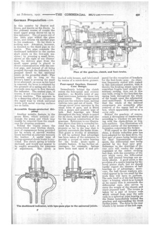
With regard to the live-axle machine, d double reduction gear has been adopted for the final drive, the first pair of gears being bevels and the final transmission through spurs, the differential case being carried by the final spur gear. Reference to the drawings of the rear axle will render the reader cognizant of the rather striking fact that, with the exception of the pair which carry the differential case, ball journal bearings are entirely absent. A good point is the provision of a centre bearing for the bevel pinion shaft, but we should hardly regard the absence of ball bearings as of advantage moreover, the ball thrust washers provided appear to be too small for the work they will have to perform. The axle itself is of the full floating type : a, forging, which is so formed at its centre that it surrounds the differential case, also serves to carry the weight of the chassis and super imposed load. The torque is taken by a pair of torque rods which extend from near the axle ends to a spherical joint bearing on the frame immediately behind the gearbox and surrounding the front• cardan joints. The drive to the rear wheels is by means of the hub caps.