A Hydraulic Torque-converter
Page 76

If you've noticed an error in this article please click here to report it so we can fix it.
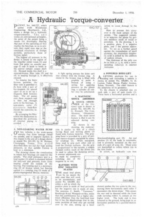
PATENT No. 640,727, which aornes froin litrockhouse Engineering: (Southport), Ltd., shows a design far. , a hydraulic torque-converter. T h e, u•n it works pn conventional principles, the point ,of. the ,patent being a means fdr thoroughlyfiltering :' tht papt of the operating oil that reaches the bearings, so as to prevent their rapid wear due to the, continued circulation of foreign naiades, particularly those of ferrous metal.''' The highest oil pressure in the device is (ound lw the region of the impeller outlet vanes (1) and tram this paint an annular passage (2 and 3) leads to holes in the central /tabular . output shaft (4). "Housed inside this shaft is a sintered-brenze filter -tube (5)' and the lf seeping threugh it, is effectively cleaned.
To remove the finest ferrous 'paitieles, the filter lithe is provided in. iTs, bore With a pair of bar-magnets (6) spaced aOart so as to set up. a , magnetic field between then). • The oil paSses over. these . magnets and • is then led . 'through, ports to the bearings. 'A npp-return. valve• p e v.e n t s back-flow: shOuld the convertet;.be _ over-run.'
By arranging the-filter within the theehanism as described-the provision Of 'external piping is avoided. ,' A NON-LEAKING WATER PUMP yenf" vehicles is the water-pump entirely free from leakage -±aVad' the spindle, and to improve matters in , this respect -is the aim of a design shown ,(11 patent No: 641,183,bY M. Hongne, Champigny, France. The 'glanc described does not tall for high sealing piessures, so that spindle friction is kept to a ,minimum.
The drawing shows the construction in which, ball bearings are uted:for the spindle. The chief stationary -seal. is a lead washer (1) which is clamped behind the baIL-race and prevents water from seeping round the "outiide Of the bearing. The-running seal is a stationary ring (2) -'of bronze which has bearing against it a running ring (3) Made of a plaitie-impiegnated fibrous material.
A light spring presses the latter unit into contact with the bronze ring. A recess.in the bronze ring is filled with graphite at point 4. Instead of using a spring for applying pressure to the plastic ring, a cylinder of rubber may be substituted.
A MAGNETIC SHOCK ABSORBER
A SHOCK ABSORI-IBER of the fric
tional type is shown in patent No. 641,189, by G. Pownall, The Cote.
Alveston, Gloucestershire. The mostnovel feature is that-it can be adjusted during run-• ning.
As shown in the drawing, the construetion is similar to Mat of a clutch
baying fixedandplates (1)
faced with friction naterial, The grip
ping orce is provided by a pair of pottype electro-magnets energized by annu
lar' windings: (2). . When energized, these tend to grip each other and s6 load the friction surfaces. As,the grip is proPortional' to the Current, a simple rheostat within reaCh:of the driver Can be -used to adjust the damping aCtion. A coarser adjustment can be made by completely switching one of the magnets in or out,
BATTERY WITH ZINC NEGATIVE PLATES
THE usual lead plates are by no means the only ones' that will work
as an accumulator, and patent No. 640,889, describes a cell in which the positive plate is made of lead peroxide, but the negative one is made of zinc. The patentee, C. Smith, " Yeoveney," Roxburgh Road, Westgate-on-Sea, states that this combination has a higher electrical efficiency than the lead-lead type but it has the disadvantage that in use, some particles of lead may get carried over to the zinc, setting up a local action to cause_ damage 10_ the cell. •
How to`• prevent this carryover is the main subject of the patent. The suggested reinedy is to separate the plates by. porous members made of Woodor porcelain. In the drawing; is a positive plate, 2 a negative Plate, and 3the porous seParator. To act as a„ further guard against the transmission of small particles, the electrolyte (sqlphuric acid) is jellied by the addition
of spdium silicate. ,
• The thickness of the jelly can :be as little as -fk, in, with, a corresponding reduction in internal resistance.
A POWERED _BODY-LIFT
A LIFTING platformfor use . in P'lloading and unloading a vehicle is shown in patent No. 640,885,. by D. Layton, Tudor House, Poplar Avenue, Eaton, Norwich. The chief feature is the simplicity of its geometry.
To the chassis is attached one oa each side, a patr of cam tracks (1). These have a horizontal -portion and a downward-sloping part (2), An end
portion (3) of the body is reriacivable, and is pivotally mounted on the rear ends of a pair of arms (4). These arms are journalied to rollers Which riin in the cain `tracks.
In action, an 115-tdraulie raln (not
shown) pushes the two arms to the rear, moving them horizontally until roller 5 encounters the down-slope.' This causes the rear end to descend while the front ends carrying Toners 6, -remain the higher level. The body end is thus lowered to the ground, being kept in an horizontal position by a parallel-motion rod (7).


