


Rubber Suspension for Trailing Axles
Page 64
If you've noticed an error in this article please click here to report it so we can fix it.
.1-1. A SUSPENSION system employing
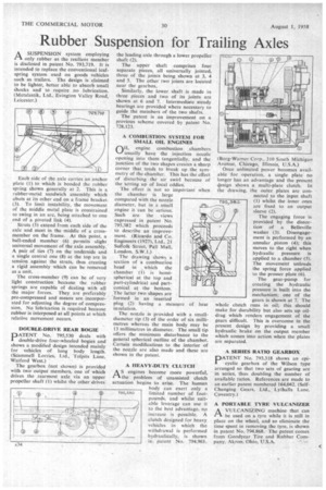
only rubber as the resilient member is disclosed in patent No. 793,719. It is intended to replace the conventional leafspring system used on goods vehicles such as trailers. The design is claimed to be lighter, better able to absorb small shocks and to require no lubrication. (Metalastik, Ltd.. Evington Valley Road, Leicester.) Each side of the axle carries an anchor plate (1) to which is bonded the rubber spring shown generally at 2. This is a rubber-metal sandwich assembly which abuts at its other end on a frame bracket (3). To limit instability, the movement of the middle metal plate is constrained to swing in an arc, being attached to one end of a pivoted link (4).
Struts (5) extend from each side of the axle and meet in the middle of a crossmember on the frame. At this point. a ball-ended member (6) permits slight universal movement of the axle assembly." A pair of ties (7) on the underside and a single central one (8) at the top are in tension against the struts, thus creating a rigid assembly which can be removed as a unit.
The cross-member (9) can be of very light construction because the rubber springs are capable of dealing with all the major forces. They are preferably pre-compressed and means are incorporated for adjusting the degree of compression. No lubrication is required because rubber is interposed at all points at which relative movement occurs.
DOUBLE-DRIVE REAR BOGIE
PATENT No. 795,530 deals with double-drive four-wheeled bogies and shows a modified design intended mainly for vehicles of long body length. (Scammell Lorries, Ltd., Tolpits Lane,
Watford West.) ' The gearbox (not shown) is provided with two output members, one of which drives the rearmost axle via an upper propeller shaft (1) whilst the other drives the leading axle through a lower propeller shaft (2).
The upper shaft comprises four separate pieces. all universally jointed, three of the joints being shown at 3, 4 and 5. The other two joints are located near the gearbox.
Similarly, the lower shaft is made in three pieces and two of its joints are shown at 6 and 7. Intermediate steady bearings are provided where necessary to guide the members of the two shafts.
The patent is an improvement on a previous scheme covered by patent No. 728,123.
A COMBUSTION SYSTEM FOR SMALL OIL ENGINES
Qit engine combustion chambers usually have the injection nozzle opening into them tangentially, and the junction of the two shapes creates a sharp corner that tends to break up the symmetry of the chamber. This has the effect of disturbing the air swirl because of the setting up of local eddies.
The effect is not so important when the chamber is large compared with the nozzle diameter, but in a small engine it can be serious. Such are the views expressed in patent No. 795,382 which proceeds to describe an improvement. (Ricardo and Co. Engineers (1927), Ltd., 21 Suffolk Street, Pall Mall, London, S.W.1.) The drawing shows a section of a combustion head in which the chamber (1) is hemispherical at the top and part-cylindrical and partconical at the bottom. The latter two shapes are formed in an inserted plug (2) having a measure of heat insulation.
The nozzle is provided with a smalldiameter tip (3) of the order of six millimetres whereas the main body may be 13 millimetres in diameter. The small tip offers the minimum disturbance to the general spherical outline of the chamber. Certain modifications to the interior of the nozzle are also made and these are shown in the patent.
A HEAVY-DUTY CLUTCH
AS engines become more powerful, the problem of unassisted clutch actuation begins to arise. The human body can exert only a limited number of foot-. pounds, and whilst suitable leverage can use it to the best advantage, no increase is possible. A clutch designed for heavy vehicles in which the withdrawal is performed hydraulically, is shown in, patent No. 794,961.
Borg-Warner Corp., 310 South Michigat Avenue, Chicago, Illinois, U.S.A.) Once unlimited power becomes available for operation, a single plate no longer has an advantage and the present design shows a multi-plate clutch. In the drawing, the outer plates are connected to the input shaft (1) whilst the inner ones are fixed to an output sleeve (2).
The engaging force is provided by the distortion of a Belleville washer (3). Disengagement is performed by an annular. piston (4); this moves to the right when .hydraulic pressure is applied to a chamber (5). The movement unloads the spring force applied to the presser plate (6).
The gear-pump for creating the hydraulic pressure is built into the mechanism; one of the gears is shown at 7. The whole clutch runs in oil: this should make for durability but also sets up oildrag which renders engagement of the gears difficult. This is overcome in the present design by providing a small hydraulic brake on the output member which comes into action when the plates are separated.
A SERIES RATIO GEARBOX
PATENT No. 793,318 shows an epicyclic gearbox of the Wilson type arranged so that two sets of gearing are in series, thus doubling the number of available ratios. References are made to an earlier patent numbered 164,042. (SelfChanging Gears, Ltd., Lythalls Lane, Coventry.) A PORTABLE TYRE VULCANIZER A VULCANIZING machine that can 1-1 be used on a tyre while it is still in place on the Wheel, and so eliminate the time spent in removing the tyre, is shown in patent No. 794,868. The patent comes from Goodyear Tire and Rubber Company, Akron, Ohio, U.S.A.