


AN ELECTRIC VEHICLE IMPROVEMENT.
Page 30
If you've noticed an error in this article please click here to report it so we can fix it.
A Resume of Recently Published Patents.
An invention which, if it fulfils all the claims which are made for it, should, in its .applioation, assist very considerably in the developing and popularizing of the electric vehicle, is described in potent specification No. 181,432. It has for its object the provision of improved means for enabling the vehicle driving motor to be used also for recharging the accumulator. It embodies improved methods of wiring, Whereby this object can be obtained.
Road motor vehicles of the type in question usually operate, as the patentee points out, from an accumulator system of from 60 to 80 volts. The normal voltage at which direct current is supplied in private houses or garages is about 220. Hitherto, it has been impossible to recharge the accumulator economically from a 220-volt system, except by the use of an expensive motor generator set.. By this invention, however, the owner will be able to utilize the driving motor of his vehicle instead of an expensive generator set, and . will be able with it to recharge his batteries with high efficiency from a 220-volt „supply. By this means, in addition to avoiding the capital cost of a separate motor generator set for recharging, the inventor claims that it will be possible to utilize the supply current at 220 volts or thereabouts snore economically than is possible with an ordinary set of this-kind.
An additional advantage gained by this invention is that the energy of the vehicle itself can be utilized for recharging the accumulators whenever the brakes are applied or when running down-hill.
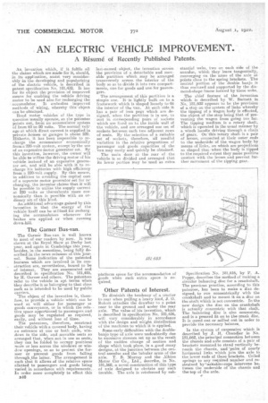
The Garner Bus-van.
The Carta]: Bus-van is well known to most. of our readers by now. It was shown at the Royal Show at Derby last year, and again at Cambridge this year, besides, in the meantime, being fully de scribed in the news columns of this jour nal. Some indication of the patented features -which are involved in its con struction are, nevertheless, bound to be of interest. They are enumerated and described in specification No. 181,485,
by H. Corner and others. The patentees refer to the vehicle in apt terms when they describe it as beelonging to that class such as is intended to be used by public carriers.
The object of the invention is, therefore, to provide a vehicle which can be used at will either for passenger es goods conveyance, or in which the rela• tive space apportioned to passengers and goods may be regulated as required, easily, and without loss of time. • The patentees, therefore construct their vehicle with a covered body, baying an entrance at one or both ends, win dows in the side, and movable seats so arranged that, When not in use as seats,.
they can be folded to occupy positions more or less across the windows ar window openings, so as to protect the for noer or prevent goods from falling through the latter. The arrangement is such that it allows of the relative space allotted to passengers and goods being varied in accordance with requirements. In order snore completely to effect this B46 last-named • object, the invention covers the provision of a detachable and movable partition which may be arranged transversely across the interior of the body so as to divide it into two comportments, one for goods and one for passen gers. .
The arrangement of this partition is a simple one. Itis lightly built on to a framework which is shaped loosely to .fit the interior of the van. At each side it has a pair of iron pegs which are designed, when the partition is in use, to rest in corresponding pairs of sockets which are fixed on to the inside wall of the vehicle, and are arranged one set of sockets between each two adjacent rows of seats. By the selection of a suitable set of sockets, therefore, all needful variation in the relative proportions of passenger and goods capacities of the vammay easily and quickly be obtained.
The main door atthe roar of the vehicle is so divided and .arranged that its lower portion may be used as extra
platform space for the accommodation of goods when such extra space -is required.
Other Patents of Interest.
To diminish the tendency of a tractor to rear when pulling a heavy lciad, J. G_ Bukolt attaches the drawbar to a point near to the ground. and under the rear axle. The value of his invention, which is described in-specification No. 181,456, will vary considerably in accordance with the design and weight distribution of the machines to which it is applied.
Scene early difficulties with the doublebanjo type of axle were undoubtedly due to excessive stresses set up as the result of the sudden change of section and shape which took. place, in a good many 'designs, at the junction between the central annulus and the tubular arms of the axle. T. B. Murray and the Albion Motor Car Co.' Ltd., describe, in No. 181,568, a novel construction of this type of axle designed to obviate any such trouble. The axle is reinforced by sub
stantial webs, two on each side of the annulus, which they leave tangentially, converging on the arms of the axle at points dose to the spring brackets. The central portion of the double banjo is thus enclosed and supported by the diamond-b.ape frame formed by these webs.
The chief feature Of the invention whicili is described by W. Barnett in No. 181,602 appears to be the provision of a stop on the system of links whereby the tipping of a wagon body is effected, the object of the stop being that of preventing the wagon from going too far. The tipping medium is a rotary shaft, which is 6perated in the usual manner by a windh handle driving through a chain of gears. On-this rotary 'shaft is a pair of levers, connected at their Outer ends to the underside of the wagon body by means of links, on which are projections so shaped that when the body is tipped to the required extpnt they make positive contact with the levers and prevent further movement of the tipping gear.
Specification No. 181,616, by P. A. Boppe, describes the method of making a circular balancing disc for a crankshaft. The previous practice, according to this patentee, has been to make a disc designed, to run concentrically with the crankshaft and to mount it on a disc on the shaft which is not concentric. In the new design the disc on the crankshaft is actually concentric with that shaft. The balancing disc is also concentric, and is a pressed fit on to the crank disc. It is cored out or milled out in order to provide the necessary balance.
In the-system of suspension which is described by J. H. Chandler in No. 181,662, the principal connection between the chassis and axle consists of a pair of brackets mounted to stand vertically beneath the chassis, and 'pairs of nearly horizontal links which join the axle to the lower ends of these brackets. Coiled springs to any required number and restrained by;staitablet.cups intervene between the underside of the chassis and the top of the axle.