New Forward-control 10-12-cwt. Van
Page 110

Page 115

If you've noticed an error in this article please click here to report it so we can fix it.
Original Features in Latest Standard Include Chassis Frame in Two Parts and Unusual System
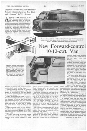
APARTICULAR distinction of the Atlas forward-control 10-12-cwt. van, announced today by the Standard Motor Co., Ltd., Coventry, is that it is the first commercial vehicle produced by the concern based on an original concept, as distinct from the conversion of a private car. Moreover, the vehicle has a number of outstanding features, which include a chassis frame built in two sections to promote easy maintenance, independent front suspension units
designed to increase roll resistance and a commendably small turning circle.
Payload rating is 10-12-cwt. in addition to the driver and passenger. The dry weight of the vehicle is 181 cwt., whilst its kerb and gross weights are respectively 19 cwt. and 34 cwt.
Power is derived from a 948 c.c, oh-v. four-cylindered petrol engine, as fitted to the Standard 10-h.p. car and 6-cwt. van. The compression ratio has been reduced from 8 to 1 to 7 to 1 so that commercialgrade fuel may he used, and its output has been derated from 37 b.h.p. to 35 b.h.p.
Power-to-weight ratio of the vehicle, based on the net output of the engine and the gross vehicle weight, is 0.9 cwt., whilst the payload percentage of the gross weight is 35.
A 10-gal, fuel tank is located behind the wheel-arch on the near side. The capacity of the cooling system is 71 pints
E20 and the electrical system is 12v.A combined element-type air cleaner and silencer is replaced by an .oil-bath cleaner on export models.
Excluding the space at the side of the driver, the payload capacity is 180 Cu. ft.. The load-carrying section has a floor area of 42 sq. ft., a length of 7 ft. 8 in., a floor-to-roof height of 4 ft. 7 in. and a width, excluding wheel-arches, of 5 ft. 3 in. The loading height is 1 ft. 101 in., whilst the width and height of. the rear door are 3 ft; 6 in. and 3 ft. 111 in. respectively. There-is a bulkhead behind the driver.
The engine is inclined some 10° to the near side, thus reducing the bonnet height. The bonnet is insulated and has detachable side panels.
An adjustable seat for the driver is mounted on one of the raised sections of the floor, in line with the engine cover; which are formed by the wheel-arches.
There is ample room between the wheel-arches and bulkhead for the spare wheel and battery.
At floor level the distance between the engine cover and the front panel is about 10 in,, which gives easy access to the drive'r's seat from the near side. Good visibility is provided by •a curved full-width windscreen. Maximum internal width of .the cab is 5 ft. 21 in.
A direct-acting gear lever has a cranked extension which enables the driver ro manipulate the gears with his left hand (or right hand on the left hand.drive model s) approximately in line with his body. The ignition switch, choke control and starter button are mounted behind the engine cover, whilst the speedometer, fuel gauge and warning lights of the oil-pressure and ignition systems are in a central dial.
Located under the dash to the right of the steering column, the hand brake lever is neatly arranged to obviate obstruction.
In standard form the cab doors are hinged to the windscreen pillars and provide an opening width of about 2 ft. 4 rn. at step level. The doors are fitted with sliding windows and pivoting ventilators. A scuttle ventilator is also a Standard feature. A Weathershield's roof vent is fitted to the goods compartment.
Available as an optional extra, a Smith's heater unit is located behind the detachable front grille. Both the temperature of the air and the volume of the air flow can be controlled from the dash, and
the heater can be used to supply windscreen demisters.
Sliding cab doors, which are flush when closed, are also available as an optional extra. When open the doors lie along the outside of the body.
Other interior details include a rubber floor covering in the cab, a swaged-type floor in the goods department designed to withstand heavy loading, a cab roof light with integral switch, and a passenger foot rest which provides a stowage for the starting handle. A 'passenger seat is available as an extra.
Exterior fittings include a front bumper finished with porcelain ceramic paint (curved rear -side bumpers are supplied as an extra), and a recessed rear number plate.
Engine power is transmitted through a hydraulically operated single-dry-plate clutch of 6+, in. diameter to a four pd synchromesh gearbox. Gear ratios arc: Top, 1 to 1, third, 1.454 to 1, seCond 2.46 to 1, and bottom and reverse, 4.271 to 1.
The propeller shaft is mounted in needle-roller universal joints, and the rear axle incorporates semi-floating shafts and a hypoid-bevel final drive giving a ratio of 6.6 to I. This axle was specifically designed for the van.
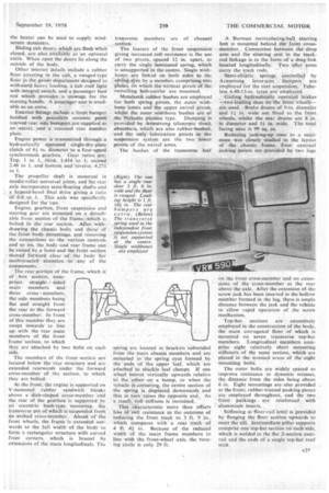
Engine, gearbox, front suspension and steering gear are mounted on a detachable front section of the frame. Which is bolted to the rear section. After withdrawing the chassis bolts and those of the &brit body mountings, and removing the connections to the various controls and so on, the body and rear frame can be raised by a hoist and the front section moved forward clear of the body for unobstructed attention to any of the components.
The rear portion of the frame, which is of box section, com prises straight sided main members and three cross members, the side members being flat and straight from the rear to the forward cross-member. In front of this member they are swept inwards to line up with the rear main members of the front framesection, to which they are attached by two bolts on each side. •
The members of the front 'section are located below the rear structure and arc extended rearwards underthe forward cross-member of the section. to which
they are bolted.
At the front, the engine is supported on V-mounted rubber, sandwich 'blocks above a dish-shaped cross-member and the rear of the gearbox is supported by an eccentric bush-type mounting. the transverse pin of which is stispended from an arched cross-member... Ahead of the front wheels, the frame is extended outwards to the full width of the body to form a rectangular structure with curved front corners, which is braced by extensions of the main longitudinals. The
transverse members are of channel section.
The feature of the front suspension giving increased roll resistance is the use of two pivots, spaced 12 in, apart, to carry the single laminated spring, which is unsupported in the centre. Single wishbones are linked on both sides to the sifiring eyes by a member, comprising two plates, on which the vertical pivots of the swivelling hub-carrier are mounted.
Metalastik rubber bushes are employed for both spring pivots, the outer _wishbone joints and the upper swivel pivots, whilst the inner wbborie bushes are of The Nylastic plastics type. Damping is provided by Armstrong telescopic shock .absoisbers, which are also rubber-bushed, and the only lubrication points in the suspension system arc the two lower ,pivots of the swivel arms.
The bushes of the transverse leaf
spring are located in brackets subtended from the main chassis members and are .mounted in -the spring eyes formed by the 'ends of the upper leaf, which are attached to shackle leaf clamps. If one wheel moves vertically upwards relative to the other on a bump, or when the vehicle iS cornering, the centre section of the spring is displaced downwards and this in turn raises the opposite end. As
a result, roll stiffness is increased. _ This characteristic more than offsets loss of roll resistance as the outcome of reducing the front track to 3 ft. 9 in., 'Which compares with a rear track of 4 ft. CI in. Because of the reduced width of the main frame members in line with the front-wheel axis, the turning circle is only 29 ft.
A Burman recirculating-ball steering box is mounted behind the front crossmember. Connection between the drop arm and the steering arm in the trackrod linkage is in the form of a drag-link located longitudinally. Two idler. arms carry the track rods.
Semi-elliptic springs. controlled by Armstrong lever-arm , dampers are employed for the rear.suspension. Tubeless 6.40-13-in, tyres are employ ed.
Girling hydraulically operated brakes --two-leading shoe on the front wheels— are used. Brake drums of 9-in, diameter and 1.1 in, wide are fitted to the front wheels, whilst the rear drums are 8 in. in diameter and 1+ in. wide. The total faxing area is 99 sq. in.
Reducing jacking-up time to a minimum was closely studied in the layout of the chassis frame. Four external jacking points are provided by two logs on the front cross-member and on extensions of the cross-member at the rear above the axle. After the extension of. the screw jack has been inserted in the hollow member formed in the lug, there is ample distance between the jack and the vehicle to allow rapid operation of the screw .meehanism.
Top-hat sections are extensively employed in the construction of the body, the main corrugated floor of which is mounted on seven transverse top-hat members. Longitudinal members comprise eight relatively short mounting stiffeners of the same section, which are placed in the stressed areas of the eight mounting bolts.
The outer bolts are widely spaced to improve resistance to dynamic stresses, the distance from the sides being about 6 in. Eight mountings are also provided at the front; rubber-treated packing pieces are employed throughout, and the two front paekings . are reinforced with aluminium inserts. , Stiffening at 'floor-rail level is provided by flanging the floor section upwards to meet the sill. Intermediate pillar supports comprise one top-hat section on each side, which is welded to the flat Z-section cantrail and the ends of a single top-hat roof stick.


