


A Resume of Recently Published Patent Specifications A Space-saving Two-stroke
Page 50
If you've noticed an error in this article please click here to report it so we can fix it.
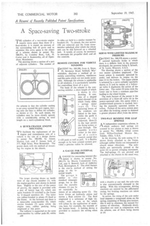
THE cylinders of a two-stroke engine require more space than those of a four-stroke, it is stated, on account of the surrounding belt of ports and to minimize this extra space is the object of a scheme shown in patent No. 588,951, by Crossley Bros., Ltd., H. Carter and A. Kenworthy, all of Openshaw, Manchester.
The drawing shows a section of a pair of adjacent cylinders. The essence of the scheme is that the cylinder casting is cut away around the port region, leaving only the liner to define the cylinder, as shown at (1). By such means, the cylinders may be more closely spaced, with a considerable saving in total length on a multi-cylindered block.
A QUICK-CHANGE ENGINE MOUNTING
TO facilitate the replacement of the flgine and transmission unit of a vehicle is the aim of a design shown in patent No. 588,948, by Jensen Motors, Ltd., .and F. Jensen, both of 377, High Street, West Bromwich. The patent deals with the method of mounting the engine in the chassis.
The larger drawing shows an inside view of one chassis member (1), with the engine-gearbox unit shown in dotted lines. Slightly to the rear of the centre of gravity, the engine is provided with a pair of lateral lugs (2), which rest upon brackets (3) attached to the frame by U-shaped members (4). The latter are rubber-bonded to plates (5) fixed to the frame. At the forward end there is a removable cross-member (6), which carries brackets (7) upon which the engine rests, rubber packing being employed at this point.
The radiator is supported on the same cross-member by rubber pads (8), whilst A40 its sides are held in a similar manner by brackets (9). To detach, the rear screws (10) are removed and the front crossmember unbolted, after which the whole unit can be slid forward on a wheeled jack. It would, of course, be necessary to uncouple the propeller shaft and all the controls.
REMOTE CONTROL FOR VEHICLE WINDOWS
PATENT No. 589,286, from A. Smye, 39, Sevenstar Road, Solihull, Warwickshire, discloses a. method of remotely controlling windows, ventilators and like units which are not easily accessible. Although the scheme is applicable to all windows, it is particularly suitable for controlling those of a p.s.v.
The basis of the scheme is the connecting member, a short length of which is shown in the drawing. It consists of a shaped metal channel (1) in which freely, slides a springy metal tape (2). The operating levers of the windows are linked to the tape, whilst the guide is screwed to the bodywork. Slots (3) in the tape permit the fixing screws to pass through. The assembly w orks rather in the manner of a cable control, except that t will push as we I as pull. It is flexible enough to be bent around corners provided a genuine radius be allowed.
A GAUGE FOR INTERNAL DIAMETERS
A GAUGE for measuring internal diarA meters is shown in patent No. 589,173, by Morris Commercial Cars, Ltd., and A. Boswell, both of Adderley Park, Birmingham, 8. The chief feature is the simr.le method of setting the gauge to the 7equired length.
The gauge is similar to t h e standard telescopic gauge, but in this case the movable element (1) can be set outwardly by means of an adjusting screw (2). The latter forms an hydraulic piston and moves a fluid column (3). The fluid employed is a substance of high viscosity, such as wax or fat which will soften by the 'application of moderate heat, for example, the warmth of the human. hand. A locking device is provided to maintain the setting when made.
SERVO WITH LIMITED MAXIMUM PRESSURE
PATENT No. 588,970 shows a powerassisted hydraulic brake in which there is a definite limit to the pressure developed, the patentee being S. Schnell, of St. Louis, Missouri, U.S.A.
The drawing shows a section of the two master cylinders employed. The lower piston is manually operated by pedal, and delivers its output via the pipe (1) to the brakes.. The upper piston is actuated by a servo cylinder (partially shown at 2) and by means of a followup valve it duplicates the action of the lower one. The outlet (3) joins with the lower one to form a common pipe-line leading to the wheel brakes.
" The main feature of the patent is the provision of a blow-off valve (4) in the power-operated side; this opens when a predetermined pressure is reached, leaving the manually operated system in action. Failure of the servo system does not affect the braking, except to demand a greater physical effort from the driver.
TWO-WAY. BENDING FOR LEAF SPRINGS
AN independent suspension scheme, in which ordinary leaf springs are stressed in two planes at once is shown in patent No. 588,866, which comes from Willys-Overland Motors Inc.,
Toledo, Ohio, U.S.A. • In the drawing, the axle casing (1) is shown firmly attached to the frame, although rubber blocks are interposed to
absorb minor vibrations. The axleshafts are universally jointed at the point (2) to permit swinging movement. The leaf-springs (3) are pivoted and attached to the chassis in the usual way,
with a shackle at one end; the axle tube is also conventionally clamped to the spring. With this arrangement, driving reactions are resisted by the differential casing, but braking reactions are taken by the springs.
In action, the rising of the axle under load imposes a compound stress on the spring, consisting of flexing plus torsion; this is said to eliminate the natural frequency of vibration. Hydraulic shockabsorbers are used in conjunction with the scheme, one of them being shown at (4)