


Two-axled B.U.T. Trolleybus
Page 32
Page 33
If you've noticed an error in this article please click here to report it so we can fix it.
A Trolleybus Chassis Designed to Give Exceptional Riding Comfort and a Long Service Life with a Minimum of Maintenance
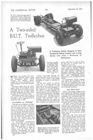
WITHIN a few months of its threeaxled trolleybus chassis going into production, British United Traction, Ltd., Hanover Square, London, W.I, is now producing a twoaxled trolleybus on the same assembly lines.
Developed largely from the A.E.C. Regent Mark III oil-engined chassis, with which many of its parts are interchangeable, the new two-axled vehicle has been designated the 961T. chassis for both 7-ft. 6-in. and 8-ft. width.
The overseas version, with a width of 8 ft. or 8 ft. 6 ins., has been designated the ETI3/ 1, and is estimated to be in production early in 1948.
Accessibility on " Docking "
Although not revolutionary in design, the layout of the 961T. chassis has received careful attention to facilitate ease of maintenance, and an inherent regard for materials of high specification and adequate lubrication of working parts should earn praise from the most meticulous operator. The driver has also rebeived due consideration in that the foot controls have been designed to give a short movement and freedom from draught.
A conventional channel-section frame, 11 ins, deep and I-in, thick, is supported by tubular cross-members with tubular members to carry the motor. A flitch plate is riveted in position over the front axle for additional strengthening, the frame being inswept at this point to provide a turning circle of 58 ft.
A30 Timken taper-toiler bearings are fitted to the hubs of the front axle, an H-section beam, which is well graded throughout its length, to withstand all stresses.
On the later models an anti-roll torsion bar is mounted off the axle beam with tie bars reaching up to the frame; this is an inverse procedure to that employed in rear-axle mounting. The B.U.T. air-brake cylinders are mounted directly over the king pins to avoid steering interference, and special taper-roller thrust bearings are fitted to the swivel pins. The brake cams are provided with lubrication from a Tecalemit Syndromic unit, special oil seals being fitted to the cam ends of the lever to prevent oil reaching the brake facings, whilst there is a drip tray below the king pins to prevent waste oil dripping on to the tyres.
Floatex rubber bushes support the motor, which is mounted amidships from a rigid tubular sub-frame. Motors and other electrical equipment by Crompton Parkinson, Ltd., General Electric Co., Ltd. English Electric Co., Ltd., and Metropolitan Vickers Electrical Co., Ltd., are optional for this chassis.
A large-diameter Layrub propeller shaft carries the transmission to the rear axle, the transmission line being straight under half-load conditions, with two degrees deflection either way under full or no-load conditions.
Low Floor Level
Using a three-degree oblique worm drive enables the differential housing to be well tucked away to the left side, permitting a low and unobstructed floor level. An option of 9.7 or 10.3 to I final drive ratio is available, the former ratio being considered standard and the latter being for special applications.
The 8k-in. centres worm gear and road wheels are carried on taper-roller bearings with bellows-gland oil seals, having renewable thrust washers. Fully floating axle shafts with involute splining have a greatly increased fatigue factor over the conventional parallel faced splines.
With 6-in, wide brake shoes and 161-in, diameter drums, a large friction area is maintained for the rear r.;le, whilst 3-in, wide shoes on the front axle give an effective friction area of 474 sq. ins, for both axles. The fin.-thick brake facings are operated through high-lift camk a factor which eliminates re-splining the operating lever throughout the life of the facing. Scissorstype adjusters are common to both front and rear axles, giving easy access and rapid adjustment, A notable feature of the chassis is its soft suspension, 11-leaf springs being employed at the front and 20-leaf springs at the rear. Both sets of springs are of exceptional length, being 4 ft, 2 ins. at the front and 5 ft, 2 ins. at the rear, the width in both eases being ins_ A heavy-duty torsion bar at the rear is connected from the frame to the.Springtrackets by sturdy tie-bars.
Following established BALT. practice, air to the compressor is taken through a filter and tubular cross-member to dampen out compressor pulsations. Either a Westinghouse or Peters corn
• i.t.-eSsor is used, according to the
customer's requirements. The h.)). ss0-volt'motor-driven compressor , is carried on an outrigger bracket from the frame, which is mounted on Silentbloc bushes to Minimize vibration on the chassis frame. 'A pressure of 70 lb. to 90 lb. per sq. in. is mainMined by the 5-cubic-ft. compressor unit, the pressure being controlled through an eieetro-pneumatic valve operating from the driver's cab. '
A patented 43.75 cubic-ft. capacity reservoir incorporates a control vale, check valve, safety valve, drain cock and expansion chamber. The whole air system is of simple layout, which makes possible a minimum number of insulation points, a further point being that only one rubber connection is required in the pressure pipeline, that being to the front brake assembly.
Gauges situated in the cab indicate
reservoir and brake-cylinder pressures. A " Stop" signal and bell warn the driver when the .pressure falls -below 40 lb. per sq. in. pressure. -With the exception of the compressor Valves, all other salves throughout the pneumatic system are of stainless steel and are on synthetic rubber seatings, thus eliminating air leakage through foreign matter between valve and seating.
. For the air supply solid-drawn steel tubes with B.U.T. cone fittings are employed throughout the chassis in conjunction with a 7-ply hose for the front axle feed.
It is claimed that the hand brake can decelerate the bus of 8 tons gross weight at a rate of 9.5 ft. per sec, per sec., equivalent to 30 per cent. efficiency, whilst the foot brake decelerates under similar conditions at a rate of 16.4 ft per see. per sec., equivalent to 51 per cent. efficiency. Initial movement of the brake pedal operates through two stages of the rheostatic braking before the air pressure is applied, thus reducing brake facing wear.
The steering box is set well forward on the frame to give maximum visibilty to the driver; worm-and-nut steering is employed, with the B.U.T. dual-purpose ball-bearing mounting embodied in the head of the steering column.
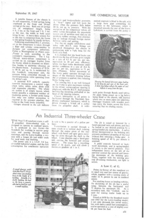
Chassis lubrication to all points is facilitated through the Teta:len-tit Syndromic mechanical lubricator, which is driven through a V-belt off a pulley from the propeller shaft. A wide
necked reservoir is fitted in the cab, with a large bore pipe connecting the reservoir to the lubricator, which is mounted towards the rear of the frame. Lubricant is carried from the pump to each point through Bundy steel tubing. the pipes being preset on a ' jig before being fitted to the chassis, ahd loomed where two or more pipes are adjoining. Outrigger brackets with wooden packjogs carry the looms across the frame, ensuring that no chafing occurs.