


A Compact High-speed Dynamo D ESIGNED specially for comniercial vehicles, the
Page 30
If you've noticed an error in this article please click here to report it so we can fix it.
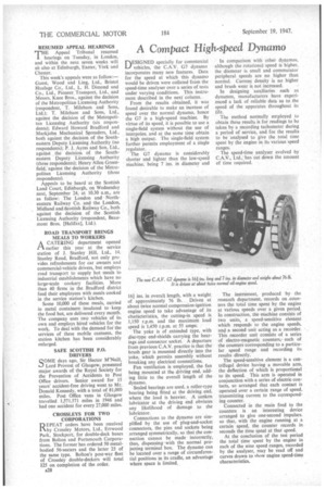
C.A.V. G7 dynamo incorporates many new features. Data for the speed at which this dynamo would be driven were collated from the speed-time analyser over a series of tests under varying conditions. This instrument described in the next column.
From the results obtained, it was found desirable to make an increase of speed over the normal dynamo, hence the G7 is a high-speed machine. By virtue of its speed, it is possible to use a single-field system without the use of interpoles, and at the same time obtain a high output. The single-field system further permits employment of a single regulator, The 07 dynamo is considerably shorter and lighter than the low-speed machine, being 7 ins, in diameter and 161 ins, in overall length, with a weight
of approximately 76 lb. Driven at about twice normal compression-ignition engine speed to take advantage of its characteristics, thecutting-in speed is 1,150 r.p.m. and the maximum load speed is 1,450 r.p.m. at 55 amps.
The yoke is of extended type, with disc-type end-shields carrying the bearings and connector socket. A departure from previous C.A.V. practice is that the brush gear is mounted directly into the yoke, which permits assembly without breaking any electrical connections.
Fan ventilation is employed, the fan being mounted at the driving end, adding little to the overall length of the dynamo.
Sealed bearings are used, a roller-type bearing being fitted at the driving end, where the load is heavier. A sunken lubricator at the driving end obviates any likelihood of damage to the lubricator. Connections to the dynamo are simplified by the use of plug-and-socket connectors, the pins and sockets being arranged symmetrically, so that the connection cannot be made incorrectly, thus, dispensing • with the normal projecting terminal box. The dynamo can be located over a range of circumferential positions in its cradle, an advantage where *ace is limited.. In comparison with other dynamos, although the rotational speed is higher, the diameter is small and commutator peripheral speeds are no higher than normal. Current density is no higher and brush wear is not increased.
In designing auxiliaries such as dynamos, manufacturers have experienced a lack of reliable data as to the speed of the apparatus throughout its life.
The method normally employed to obtain these results is for readings to be taken by a recording tachometer during a period of service, and for the results to be analysed to give the total time spent by the engine in its various speed ranges.
The speed-time analyser evolved by C.A.V., Ltd.; has cut down the amount of time required.
The instrument, produced by the research department, records on counters the total time spent by the engine at various speeds over a given period. In construction, the machine consists of two units, a speed-sensitive element which responds to the engine speeds, and a second unit acting as a recorder. This recorder unit consists of a series of electro-magnetic counters,each of the counters corresponding to a particular speed range and recording its results directly.
The speed-sensitive element is a centrifugal device having a movable arm, the deflection of which is proportional to its speed. This arm is operated in conjunction with a series of electric contacts, so arranged that each contact is operated over a certain range of speed, transmitting current to the corresponding counter.
Connected in the main feed to the counters is an interesting device arranged to give one-second impulses. so that, with the engine running at a certain speed, the counter records in seconds the time spent at that speed.
At the conclusion of the test period the total time spent by the engine in each of the nine speed -ranges, recorded by the analyser, may be read off and curves drawn to chow engine speed-time characteristics.