


SOME NOVEL GEARBOXES.
Page 30
If you've noticed an error in this article please click here to report it so we can fix it.
A Résumé of Recently Published Patents.
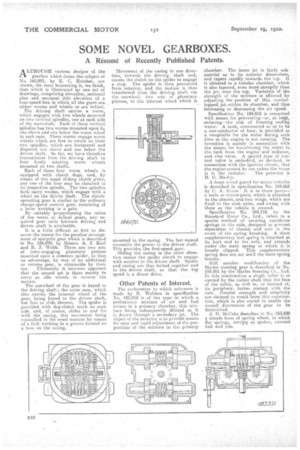
ALTHOUGH various designs of the gearbox which forms thasubject of No_ 183,951, by E. C. Hatcher, are shown, the moss Mteresting is, we think,
that which is illustrated by one set of drawings,, comprising elevation, sectional plan and secsional aids elevation of a four-speed box in which all the gears are either worms arid whee1s. or are helical.
The driving shaft carries a worm, which engages with two wheels mounted on two vertical spindles one at each side of the mainsbaft. Eacrh of these vertical spindles has two worms mounted upon it, one above and one below the warm wheel in each case_ These worms engage worm wheels which are free to rotate on their , two spindles, which are horizontal and disposed one above and one below the driven shaft. So far, we have therefore transmission from the driving shaft to four freely rotating worm wheels mounted on two shafts.
Each of these four worm wheels is. equipped with clutch dogs and, by means of the, usual sliding clutch piece, any one of the four may be clutched to its respective spindleThe two spindles both carry worms, which engage with a wheel on the driven shaft. The clutchoperating gear is similar to the ordinary changespeed control gear, Consisting of a lever working in a gate. By suitably proportioning the ratios of the worm or helical gears, any required gear ratio between driving and driven shaft is attainable.
It is a little difficult at first to discover the reason for the peculiar arrange
ment of epicyclic gear -which is described
in No. 184,070, by Messrs. A. J. Karl and B. J. Webb. There are two sets of inter-engaging planetary pinions mounted upon a common spider, so that no advantage, by way of an additional or reverse gear, is obtainable by their use. Ultimately it becomes apparent that the second set is there merely to serve as idle wheels to reverse the motion.
The sunwheel of the gear is keyed to the driving shaft ; the outer case, which also carries the internal wheel of the gear. being keyed to the driven shaft, but free to slide thereon. The spider is provided with dog-clutch teeth on each side, and, of course, slides to and fro with the casing, this movement being controlled in the usual manner by means of a fork working in a groove formed on a boss on the casing. Movement of the casing in one direction, towards the driving shaft end, causes the clutch on the spider to engage a stop. The spider is thus prevented from rotation, and the motion is thus transferred from the driving shaft via the sunwheeL two sets of planetary pinions, to the internal wheel which is .
Mounted in the casing. The last named transmits the power to the driven shaft. This provides the first-speed gear.
Sliding the casing in the other direction causes the spider clutch to engage with another in the driven shaft. Spider and -cesing are thus locked together and to the driven shaft, so that• the top speed is a direct drive.
Other Patents of Interest.
The carburetter to which reference is made by E. Wohlers in specification No. 183,962 is of the type in which a preliminary mixture of air and fuel occurs in a primary chamber, this mixture being subsequently diluted as it is drawn through a secondary jet. The object. of the inventor is to provide means for easy and rapid adjustment of the proportions of the mixture in the primary
chamber. The inner jet is fairly sub, starttial as to its exterior 'dimensions, and tapers rapidly towards the lop. It is situated in a tubular chamber, which is also tapered, even more-abruptly than the jet, near the top. Variation of the strength of the mixture is effected _bit adjusting the position of this conicaltopped jeta within its chamber, and thus increasing or decreasing the air speed.
Specification No. 184,035 is concerned with means for preventing,--or, at lea*, reducing—the risk of freezing cooling -water. A tank, constructed so 4s to be a non-conductor of heat, is provided as receptable for the water during such -time as the engine is not running. The invention is mainly in connection with the means for transferring the.water to the tank from the engine and radiator, and vice versa. A special type of control valve is embodied, so' devised, in connection with the ignition circuit, that the engine-carmot be run -unless the water
is in the radiator. The patentee is H. G. Harley.
A front-wheel gnard for motor vehicles is described in specification No, 184,063 by C. A. Stone. it is in three parts— a main or centre-Piece, which is attached to the chassis, and two wings, which are fixed to the stub axles, and swing with them as the vehicle is steered.
Specification No. 184,118, by the Standard Motor Co., Ltd., refers to a special method of securing cantilever springs to the axle, designed to prevent separation 02 chassis and axle in the event of the spring breaking. A short supplementary leaf spring is attached at ita butt end to the axle, and extends under the main spring to which it 'is loosely clipped. This supplementary spring does not, act until the main spring breaks._ Still another modification of the Merles steering gear is described in No. 183,961 by the Manes Steering Co., Ltd. In this construction a single roller is so carried by the rocker shaft that the face of the roller, as well as, or instead of, its periphery,. makes contact with the cam. Greater a and simplicity are claimed to result fromthis construction, which is also stated to enable the overall dimensions of the gear to be diminished.
J. B. McCabe describes in No. 183,890 a simple form of spring wheel, in which flat springs, serving as spokes, connect hub and rim.