


SECURING EFFICIENCYI EAM WAGON ENGINES.
Page 16

Page 17
Page 18
If you've noticed an error in this article please click here to report it so we can fix it.
CONSIDERING the large number of . steam wagons of various types in constant service, it is surprising how few persons dealing with them have really sufficient knowledge of the peculiarities of the steam engine—knowledge which would, in many cases, enable the wagons to be run.far more efficiently and economically than is the case at present. Sometimes the entire, control of a vehicle, and practically all the attention required by it, are left to the driver—admittedly, often with a. considerable degree lg. success, as the steam wagon driver is in a class by himself and takes -far more interest in his machine than the average driver of the petrol vehicle —but usually he works more or less to rule-of-thumb methods and performs certain duties more as a matter of routine than from a deep knowledge of the why and wherefore.
In this article the writer goes into the whole subject of the setting of both slide and piston type valves as employed on overtype steam wagons, at the same time explaining simply and concisely the reason for each operation. He gives a clear explanation of the reason why the lead at each end of the valves should not be equal, and points out the merits and demerits of slide valves and piston valves, explaining that the slide valve acts as a relief valve, whilst, if piston valves are utilized, separate relief valves must b& employed.
We consider that if the article be followed closely those who have dealings with steam wagons of the overtype will derive many most valuable hints which, from the point of view of the setting of the valves, as apart from that of mechanical condition, will enable full advantage to be taken of the fuel utilized and the steam produced.
We must emphasize the importance of this matter of preventing the wastage of steam and of obtaining the maximum amount of useful work from the heat units contained in the fuel. So much cutting has occurred in transport rates, that the margin between profit and loss is very small, and it is only those whose wagons are run at the highest Ditch of efficiency who can hope to better their position to any considerable degree.
Quite apart from the matter of fuel consumption, but still of great importance, particularly if the wagon be used for drawing one or more trailers, is the actual power developed by the engine ; this depends to a great degree upon the correct setting of the valves, and it is in the driver's own interest, as well as in that of the owner, that every care should be paid to this important matter.
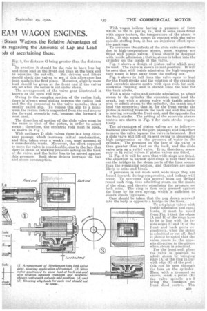
For forward travelling, looking at an engine from the e:f side, the crankpin rotates anti-clockwise. Most wagons are fitted with the Stephenson type of link valve gear, the position of the eccentric sheaves, rela-. tive to each position of the crankpin dead centre being as shown in Figs. 1 and 2, and in each position the valve is shown open to lead. Lead is the amount by which the valve uncovers the port when the piston is at the beginning of its stroke. Fig. 3 shows the position of the valve and the relation between the crankpin and eccentric sheave centre when the valve is in mid-position ; the valve overlaps both steam ports by a certain amount ; this is called the lap of the valve.
In setting the valve, both
positions of the dead Lead ponte/d
centre of the crankpin n32
must be found. To do this for the dead centre at the front, or crank end, of the .cylinder, attel with the steam chest cover off, turn the flywheel round in the anti-clockwise direction until the crosshead is near the end of its stroke; then with a centre-punch mark a dot on the crosshead guide (A), shown in Fig. 1, and with a trammel of suitable length scribe an arc on the crosshead and mark a dot on the arc (B). • . Keeping the engine in this position, and from some mark on the frame (C), again using a trammel of suitable length, scribe an are on the flywheel rim to cut at the point (D), a circle scribed on the rim. Then rotate the crankshaft until the crosshead passes through its dead point and returns to the position fixed by the trammel (A, II). Now mark the flywheel rim with trammel (C, I)) at E from centre C on the frame, divide D, E equally and mark a dot (F). Then turn the crankshaft and, using as a fulcrum the point (C) on the frame, bring the other point of the trammel to F on the flywheel. The crank is eweron dead centre for the front end, and a similar process must be done for the back end. The dead centres for each end of the cylinder are shown in Figs. 1 and 2.
The leads for each end should not be equal, because it will be seen from Figs. 4 and 5 that for equal leads the cut-off at each end of the cylinder would be different.
Actually the cut-off takes place later on the return stroke than on the forward stroke, due to the obliquity of the connecting rod. This is shown in Fig. 4, where the piston has travelled farther on its stroke than in
Fig. 5, the distance G being greater than the distance H.
In practice it should be the rule to have less -lap and more lead at the front end than at the back end
to equalize the cut-offs. But drivers and •fitters should check the valves to see. if this allowance has been made in the first place. Moreover, slightly more lead should be given at the front end if the valves are set when the boiler is not under steam.
The arrangement of the valve gear illustrated is known as the open rod type.
Owing to the complex motion of the radius link, there is always some sliding between the radius link and the die connected to the valve spindle; this is usually called slip. To reduce this slip to a. minimum the radius link is suspended from the end nearer the forward eccentric rod, because the forward is most used.
The direction of motion of the slide valve must be the same as that of the piston, in order to admit steam ; therefore, the eccentric rods must be open, as shown in Fig. 1.
With ordinary D slide valves there is a long clearance passage, which increases initial condensation, and this, taken over a week's run, must' amount to a considerable waste. Moreover, the effort required to move the valve is considerable, due to the fact that there is steam at working pressure acting on the back of the valve, and the latter has to be moved against this pressure. Both these defects increase the fuel and steam consumption.
With wagon boilers having a pressure of from 200 lb. to 250 lb. per sq. in.eand in some cases fitted with super-heaters, the temperature of the -steam is high. If this steam comes in contact with the valve spindle stuffing box, it has an injurious effect upon the packings.
To overcome theatelects of the slide valve and those due to high-temperature steam, some wagons are fitted with piston valves. These should be designed with inside admission ; that is, steam is taken into the cylinder on the inside of the valve.
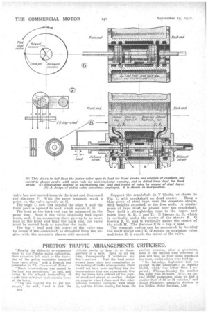
Fig. 8 shows a design of Piston valve which may be used. The valve is shown in mid-position. It will be seen•that with inside admission the high-temperature steam is kept away from the stuffing box.
Fig. 6 shows in full lines the valve open to lead for the front stroke and the relation of flee crankpin and eccentric sheave centre with open rods for anticlockwise running, and in dotted lines the lead for the back stroke.
With a slide valve and outside admission, to admit steam to the -cylinder the eccentric must lead the crank, but with a piston valve with inside admission to admit steam to the cylinder, the crank must lead the eccentric ; that is, for the front stroke the piston is moving towards the back end and the valve is moving towards the front end, and the opposite for the back stroke. The setting of the eccentric sheave centres are shown in Fig. 6 for ea.& stroke respee-. tively.
-The advantages of piston valves are as follow :Reduced clearance in the port passages and less effort to move the valve because the valve is balanced. But a slide valve will lift off its seat owing to abnormally high compression or the pressure of water in the cylinder, The pressure on the face of the valve is then greater than that on the bank, and the slide valve acts as a relief valve. It le, therefore, necessary to fit relief valves if piston valves are fitted.. In Fig. B it will be eeen that wide rings are fitted.. The objection to narrow split-rings is that they wear out the bridges'in the steam ports of the liner, sooner than the remaining portion, and therefore are more likely to seize and break.
If provision is not made with wide rings they are forced inwards during compression, and leakage will occur. To overcome this several holes are drilled round each ring, thus admitting steam on the inside of the ring, and thereby equalizingthe pressure on both sides. The ring is then only pressed against the liner by its Own spring, which is sufficient to ensure steam tightness.
Cam should be taken that the peg shown screwed into the body is opposite a bridge in the liner. To set piston valves with
inside admission and equal' leads, it must be noted from Fig. 8 that the edges (A and B) of the rings have to be in • line with the inside edges (C and D) of the frontand • back ports respectively, when the steam is admitted or cut off. And it should be noted that the valve moves in the opposite direction to the piston when steam is admitted,
For the front end, place the valve in position to admit steam by bringing edge (A) of the ring in line with edge (0) of the port; this can be seen through . the hos§ on the cylinder.
Then, with a trammel as shown, mark a point (E) the valve spindle a n d bring the crankpin on front dead centre. The
valve has now moved towards the front and decreased the distance F. With the same trammel, mark a point on the valve spindle at G.
The edge C now lies beyond the edge A and the front port is opened to lead, which equals E, G.
The lead at the back end can be measured in the same. Way. Note if the valve originally had equal leads, and, if on measuring there proves to be more lead at the front end than the back end, the valve must be moved back to equalize the leads.
The lap + lead and the travel of the valve can be found if the -crankshaft is detached from the engine with the eccentric sheave still secured. Support the crankshaft in V blocks, as shown in
Fig. 7, with crankshaft on dead centre. Hang a thin piece of steel tape over the eccentric sheave, with weights attached to the free ends. A similar piece of tape must be placed over the crankshaft. Now hold a , straightedge close to the tapes and mark lines A, B, 0 and D. E bisects A, D, which is vertically under the centre of the sheave F. G bisects B, 0, and is vertically under the centre of the shaft H. The distance E G = lap + lead.
The eccentric radius can be measured by turning. the shaft round until E, G equals its maximum value and twice E, G equals the travel of the valve.