


An Ingenious Double reduction Axle
Page 70
If you've noticed an error in this article please click here to report it so we can fix it.
AN A N improved design of double
reduction rear axle is disclosed in . patent No. 657,264, by Kirkstall Forge, Ltd„ Kirkstall, Leeds. The aim is to obtain a high reduction in the minimum of space, and this is ingeniously achieved by using the differential gear ' as part of the main drive.
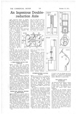
The' action will be best understood from a 'perspective diagram. The primary reduction uses a conventional bevel and crown wheel (1), but in this case the crown wheel drives the planet-. carrier (2) of an epicyclic unit. The outer annulus (3) takes the drive to one of the half-shafts (4), but he sunwheel (5) transfers its drive to the other side where a second sunwheet (6) is mounted.
On this side, the p anet-carrier (7) forms the output member, the annulus (8) being fixed to the outer casing. By this means, the normal differential action is obtained, but the gears, instead of standing idle for most of the time, can be usefully employed as a .second reduction. In addition to this diagram, the patent gives full drawings of the actual construction of the unit.
A TIIIEF-PROOF DEVICE FOR
VEHICLES
THE increased value of vehicles to-day makes the provision of some form of thief-proof device particularly useful, and as the ordinary type of ignition lock can easily be circumvented by a determined thief, a better scheme is shown in patent No. 656,363 (S. Broughton and A. Monger, 213, The Greenways, Epsom).
These inventors propose to make the ignition condenser in the form of a plug-in unit which, can easily be removed by the driver if the vehicle has to be left. For accessibility, .the plug unit is attached to the steering column as shown at 1, the removable part (2) containing the condenser. The plug is of the multi-pin type, and is arranged to break the ignition circuit in several places at once, so that even a clever thief could not arrange a temporary rig-up in order to get going. 657.264
PRODUCING HELICAL SPLINES BY BROACHING
DROACHING is a process which is becoming increasingly popular for the rapid production of complex shapes, and patent No. 657,038 shows a method Of cutting helical splines in a gear or other component. The patentee is the National Broach and Machine Company,. Detroit,. Michigan, ,U.S.A.
One, method of performing this work is to use a helical broach, and let it turn the. work as it moves through it. According to the 'patent, this method leads to inaccuracy, because the broach
A36 may not turn the work at exactly the right rate. The obvious remedy is to rotate the work by. 'gearing, but here again inaccuracy may creep in. A third method would be to use a masterhelix as a guide, but, as this would have to be as long as the broach, the scheme is
'ruled out as being 'entirely impracticable.-.
The suggested •method employs a master helix for the first part of the cut, but when the form has become well established, the master helix i.oes ouf of action. The drawing shows the setup, in which •1 is the broach, 2 the workpieee and .3 the. master helix with its surrounding nut As the ,broach, rises tck start' its 'cut, the master helix provides the necessary rotational . guidance, but once the cur is truly started, it exercises no • further guiding influence
RUBBER-BACKED CLUTCH PLATES
THE use of rubber as a backing for
clutch-plates is the subject of patent No. 656,167, by the Dunlop Rubber Co., Ltd., 1, Albany Street, London, N.W.1. The chief aim is to give smooth engagement by bringing most of the working face to bear immediately engagement commences, thus preventing judder caused by misalignment.
The scheme is appiicable to clutches in general, not particularly vehicle clutches, although these are envisaged. The drawing shows diagrammatically a pair of plates made according to the invention, the friction facings being omitted for the sake of clearness.
A plain plate (l) is one member, whilst the other consists of a similar plate provided with a bonded-on intermediate ring (2). Rubber, either natural or synthetic, is the, bonding medium. The intermediate ring is not continuous,, but is broken ,up into a number of separate ' circumferential Oates, each, being spa Cal—from its neighbour by narrow rubber spokes.
One of the claims made for this type of clutch is that the driving and driven members are substantially self-seating despite the existence of misalignment, angular difference or uneven wear.
THE SLEEVE VALVE REAPPEARS
A SLEEVE-VALVE design is shown
in patent No. 656,421 which describes a two-stroke engine fitted with a single sleeve. The patentee is G. Parker, 253, Station Road, Hayes, Middlesex.
Referring to the drawing, exhaust port S are positioned at point 1 and -an inlet belt lower down at 2. Sleeve .3 alone controls the exhaust ports, but the inlet calls for the co-operation of both piston and sleeve. The sleeve, which is thicker than ustial, is reciprocated by a pair of eccentrics (4) on the crankshaft, and is set at Such a phase angle that it assists to some extent on the power stroke. The patent mentions that the, sleeve provides at least onesixteenth of the total power output, presumably due tO the, expansive forces acting on the top edge of its comparatively thick walls.