


An Extremely Simple
Page 72
If you've noticed an error in this article please click here to report it so we can fix it.
Synchronous Clutch
A Resumd of Recently Published Patent Specifications
A DEVICE to be incorporated in a L'Agearbox for the purpose of preventing engagement between two membera until their speeds are the same is shown in patent No. 416,090, by the legal representative of the late C. M. Linley, 357, Camden Road, London, N.7.
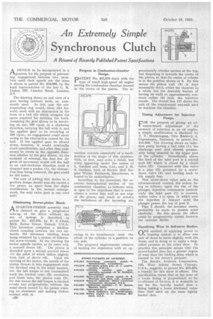
The drawing shows an end view of a gear having internal teeth, as com
monly used. In this case the corresponding dog would, when slid forward, meet with an obstruction in the form of a ball (2) which occupies the space required for meshing the teeth. Assuming the gear shown to be revolving at, say, 100 r.p.m. in a clockwise direction, carrying the ball with it, and the applied gear to be revolving at 120 rsp.m., no engagement could occur owing to the obstruction caused by the ball. If the applied gear be slowed down, however, it would eventually reach synchronism, and after that commence-to rotate in the opposite three• tion relative to the gear shown. At the mordent of reversal, the first few degrees of movement would roll the ball • in an anti-clockwise direction until it . dropped into a pocket (1), the obstruction then being removed, the gear could be slid home.
The cost of adding this device to a gearbox design should scan ely exceed a few pence, as, apart from the slight modification to the normal arrangement, the only extra part is one steel ball!
Eliminating Starter-pinion Shock.
ASTARTER-PINION assembly that is claimed to give a progressive take-up of the drive without the use of springs is described in patent No. 415,175, by P. S Claus, 3212, Eaton Tower, Detroit, U.S.A. This invention comprises a frictionclutch coupling between the two elements, the necessary binding force being obtained by a system of differential screw-threads. In the drawing the motor spindle carries, at its outer end, a screwed sleeve (4). 'The pinion is threaded upon a second screwed sleeve (1) the pitch of which differs slightly
from that of sleeve (4). Upon the starting of the motor, the inertia of the pinion thrusts it into engagement with the flywheel ring in the usual manner, hut the full torque is not transmitted until the friction cone (2) overtakes, and binds into, the pinion cone (3). By this means the full torque is reached evenly and progressively, without the usual shock caused by the pinion meeting an .abutment and making V'iolent contact with it.
c50 Progress in Combustion-chamber Design.
PNo. 415,976 deals with the type of small high-speed oil engine having the combustion chamber located in the crown of the piston. The in
vention consists essentially of a modification of the shape of this chamber. This, at first, may seem a detail, but when appearing under the names of L. Gardner and Sons, Ltd.,and J. H. S. Gardner, both of Barton Hall Engine Works, Patricroft, Manchester, is bound to be authoritative.
According to the inventors, the eccentric hemispherical section of the combustion chamber, as hitherto used, is open to the objections that it necessitates a rather thin wall at one edge of the piston, and tends to restrict the turbulence of the incoming air, owing to its transference from the whole of the cylinder to a position on one side.
The proposed improvement consists of making the depression with an ap
proximately circular section at the top, but deepening it towards the centre of the piston, so that its centre of volume is in the position shown at 2. By this means the piston wall (3) .!is kept reasonably thick, whilst the chamber as a whole has the desirable feature of having its walls at approximately constant radius (4) from the injection nozzle. The dotted line (1) shows the axis of the round-nosed end-mill used to machine the chamber.
Timing Adjustment for Injection Pumps.
L'OR the purpose of giving an ad vance-retard adjustment of the .moment of injection in an oil 'engine, a simple Modification is disclosed by T. V. Hemmingsen, Otto Rudsvej, 4, Copenhagen, Denmark,. in patent No. 414,933. The drawing shows an injection pump having a fuel inlet (1), the discharge port (not shown) presumably being situated in the upper part dl the cylinder. Immediately above the level of the inlet port is a second port (2) which is closed by a check valve (5). Connected with this valve is a pipe (3) governed by a screwdown valve (4) and leading back to the supply line.
This screw-down valve acts as the advance-retard control, the action being as follows : upen the rise of the plunger, injection commences immediately the inlet port (1) is covered, unless valve 4 is open, in which case the injection is delayed until the plunger passes the top of port 2.
Pipe 3 should, the inventor states, preferably be made to possess some elasticity. By this means the effect cd'uld be progressively varied between the extreme limits. •
Equalizing Wear in Self-servo Brakes. rINE method of applying power to braking system is to allow one pair of shoes to move slightly with the drum, and in doing so to apply a magnified pressure to the other shoe. In practice this principle means that the power-loaded shoe has a greater degree of wear than the loading shoe, which is limited to the driver's pressiire.
The Bendix Aviation Corporation, 105, VVest Adams Street, Chicago, U.S.A., suggests, in patent No. 415,424, a remedy for this state of affairs. The specification states that as the wear of a brake lining is proportional to its co-efficient of friction, it is desirable to use for the heavily loaded shoe a lining having a lesser frictional value than that used on the more lightly loaded shoe.