


STEERING GEAR FOR CATERPILLAR TRACTORS.
Page 76
If you've noticed an error in this article please click here to report it so we can fix it.
A Résumé of Recently Published Patents.
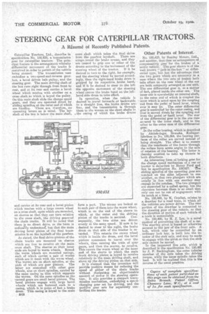
Caterpillar Tractors, Ltd., describe in specification. No. 150;455, a transmission gear for caterpillar tractors. The prim cipal feature is the arrangement whereby differential movement of the tracks is contrived in order to permit, of the vehicle being steered. The transmission ease embodies a two-speed-and-reverse gearbox, a bevel driven belt pulley, and the steering gear. The main driving shaft of the box runs right through from front to rear, and at. its rear end carries a bevel wheel which meshes with another on a cross shaft to which is keyed the pulley. On this main shaft slide the change speed _ gears, and they are operated direct by sliding spindles at the auter end of which are handles. There are, therefore, no operating levers as is lianal. The layshaft of the box is below the main shaft, and carries at its rear end a bevel pinion which meshes with a large crown wheel on across shaft, upon which are mounted, on sleeves so that they can turn relative to the cross shaft, the driving gears 'of the chain tracks. It will be noted that there is no direct deive, as the term is ordinarily understood; but that the Main driving bevel pinion of the final tiansmission is on the layshaft of the gearbox.
As stated, the final drive pinions of the -Chain tracks are mounted on sleeves which are free to revolve ohthe main cross shaft. The sleeves at their inner ends are keyed to warm wheels. Round the worm wheel's are mounted casings, each of which carries a pair of worms which are in mesh with the wenn wheel. The worms are on short spindles, at the ends of which are gear pinions. The latter are enmeshed with other gear wheels, also on short spindles carried by the same casing 'as that which supports the werms. On the same spindles as the 'second gears are small bevel pinions. The bevel pmionseengage with large bevel wheels which are fastened each to a casing, which is in paint of fact a brake drum. This easing IS keyed to the main cross shaft which takes the final drive from the gearbox layshaft. There are straps round the brake drums, arrd they are caused to grip one or other of the drums according to theenovement of the' steering wheel of the tractor. If it he ' desired to turn to the right, for example, and the steering wheel be moved accordingly, then the right-hand brake drum is gripped by its respective brake band,
and it he desired to steer to the left the opposite movement of the steering wheel causes the brake hand on thelefthand side drum to take effect
In operation, when the vehicle is desired to travel forwards or backwards in a straight line, the brake drums are.; free, and the transmission is through them to the worms on the short shafte in the casing of which the brake drums form a part. The WOMIS are locked as to each pair of them into the worm wheel, which is on. the end of the sleeve to which, at the enter end the driving pinion of the tracks, is ecured. Consequently, the two sides are driven evenly at the same speed. If now it be , desired to steer a the right, the brake drum on that side of the tractor is retarded. This retards the crown wheel which is inside the drum, and the bevel pinions commence to travel over the wheels, thus causing the train of spur gears, and then the evorrns, to revolve. This causes the-worm. wheel at the inner end of the sleeve to which the main track driving pinion is keyed to revolve relatively to the main driving shaft, and slows up the driving pinion an that side.
It is claimed that the invention will provide positive means for reducing the speed of either of the chain tracks without dissipating an objectionable amount of power in the steering operation. It also provides a compact transmission mechanism, embodying a speedchanging gear set for driving, and the positive gear sets for separately controlling the tracks.
Other Patents of Interest:
No. 150,425, by Beetley Motors, Ltd., and another,desc:ibes an arrangement. of compensating gear for the brakes of a meter vehicle. The gear shown is of the well known " jack-in-the-box " or diffeeential type, 'but has the advantage that the two sears which are necessary in a case whet a the two sets of brakes both take effect on the max wheel of the car . are both compactly arranged as one unit. The one differential gear is, as a matter of fact, placed inside the other one. The inner one is operated.by an internal shaft, to the outer end of which is coupled the -lever which is acted upon by the coupling -red from the pedal or hand lever, which . ever it may be. _ The outer differential 'gear is controlled by the outer casing, and that'is moved direct by the coupling rod from the pedal or-harid lever. The star of the differentiae gear is in the one case sentred to the inner shaft, and in the other to the outer ease of the differential gear:
In the roller bearing, which is described by Aktiebolaget Svenska, Kullagerfa,briken in No. 135,864, the bearing am-faces of the roller are curved instead of being straight. Tho effect is to ensure that the resultants of the forces through the rollers form acute angles tO the axis of rotatian of the bearing. The latter is thereby enabled to take up thrusts in both directions.
An interesting form of locking gear for the change speed mechanism of a car or tractor is described by Henry Ford and 8.on in specification No. 129627. The sliding spindles of the operating gear are . notched on the sides adjacent to one anther,, so that two plungers which are axially in line with one another may ,engage in the notches. The two plungers
are separated by a i coiled spring, but the clearance between them. s so small that only one can be out of engagement with its notch-at a tithe.
No. 150,448, by K. Crochet, relates: to a drawbar for a road train, in which all the vehicles are.power driven. The rear portion of the drawbar is connected to the steering gear of the vehicle, so that the direction of motion of each vehicle a a train is controllable.
No. 150,400, by 11. J. Lee, is a novel method of preventing the theft of a car. The steering pivot is keyed or otherwise secured to the jaw of the front axle. A bolt, which may be controlled by ael ordinary lock key, is built into the ire tenor of the stub axle, and may be made to engage with the pivot :so that the stub axle cannot he moved.
In the improved live atle.. which is described in the specification No. 150,491 , by J. F. Buckingham, the outer tubular : member of the axle takes the driving torque, while the inner spindle takes the • load. It Will be realized that this is the reverse of the usual practice.