


Patents Completed.
Page 24
If you've noticed an error in this article please click here to report it so we can fix it.
Complete specifications of the following patents will be sent to any address in the United Kingdom upon receipt of eightpence per copy at the Sale Branch, Patent Office, Holborn, W.C.
UNIVERSAL COUPLING.—Kilburn (G'ebruder Sulzer).—No. 8,782, dated 8th April, 1911.—This invention relates to universal shaft couplings of the type in which the driving member is arranged between flanges fixed on the ends of the two shafts. According to this invention driving pins mounted on each flange engage alternate blocks of circular crosssection which are mounted in cylindrical radial slots in the intermediate disc. All the parts of this coupling are made of metal, and the arrangement provides for articulation in every direction.
VALVE GEAR.—Lamplough.—No. 25,546, dated 3rd November, 1910.— This invention is applied to four-cycle internal-combustion engines of the ordinary type, and consists in the provision of rotat ng valves. A water-cooled header is provided for the cylinder and carries in it two sleeve valves arranged transversely to the cylinder; the inner ends of these are closed and are attached to a worm wheel mounted in suitable bearings. Suitable ports are provided, one in each sleeve valve, to provide communication between the cylinder ports and the inside of the valve which is open to the induction or exhaust conduit. The worm wheel is rotated by a spiral gear mounted on a shaft which is run through any desired number of headers. The sleeve valves are kept tight by a pair of seatings that are kept floating by means of circular diaphragms attached to the flanges of the seatings. For balancing purposes a pair of spiralgear shafts may be used, and these are preferably driven by spiral gear off the crankshaft. CONNECTING ROD EN D. — Knight.—No. 20,508, dated 2nd September, 1910.—In this specification there is described an improved form of big end for connecting rods. It is found in high-speed reciprocating engines that the lateral shake of the big end gives rise to a great deal of noise and vibration. This is obviated by introducing soft material between the ends of the bearing and the web of the crankshaft. A convenient substance to use is fibre, and in fitting it, a groove is cut in the bearing
metal and rings or strips of fibre are fitted therein, the fibre projecting laterally so as to form a bearing against the webs of the crankshaft.
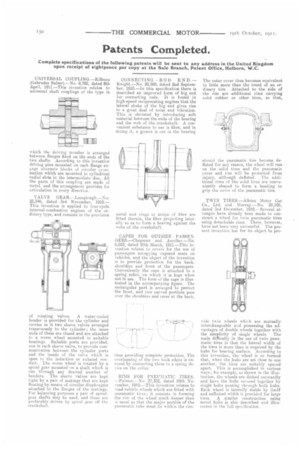
CAPES FOR OUTSIDE PASSENGERS—Chapman and Another.—No. 6,052, dated 10th March, 1911.—This invention relates to covers for the use of passengers occupying exposed seats on vehicles, and the object of the invention is to provide protection for the back, shoulders and front of the passengers. Conveniently the cape is attached to a spring roller, on which it is kept when not in use. The form of the cape is illustrated in the accompanying figure. The rectangular part is arranged to protect the front, and two curved portions pass over the shoulders and cross at the back,
thus providing complete protection. The overlapping of the two back edges is ensured by connecting them to a spring device on the collar.
RIMS FOR PNEUMATIC TIRES. —Palmer.—No. 27,352, dated 24th November, 1910.—This invention relates to road-vehicle wheels which are fitted with pneumatic tires; it consists in forming the rim of the wheel much deeper than is usual so that the major portion of the pneumatic tube must lie within the rim. The outer cover thus becomes equivalent to little more than the tread of an ordinary tire. Attached to the side of the rim are additional rims carrying Solid rubber or other tires, so that,
should the pneumatic tire become deflated for anyreason, the wheel will rim on the solid tires and the pneumatic cover and rim will be protected from injury, although deflated. The additional rims of the solid tires are conveniently shaped to form a beading to grip the cover of the pneumatic tire.
TWIN TIRES.—Albion Motor Car Co., Ltd. and Murray.—No. 28,108, dated 3rd December, 1910.---Several attempts have already been made to construct a wheel for twin pneumatic tires using detachable rims. These, however, have not been very successful. The present invention has for its object to pro vide twin wheels which are mutually interchangeable and possessing the advantages of double wheels together with
the simplicity of single wheels. The main difficulty in the use of twin pneumatic tires is that the lateral width of the tires is more than is required by the hubs for bearing surface. According to this invention, the wheel is so formed that, when the hubs are set close to one another, the tires are suitably spaced apart. This is accomplished in various ways ; for example, as shown in the illustration, the wheels are dished outwardly and have the hubs secured together by single bolts passing through both hubs. Each wheel is laterally stable by itself and sufficient width is provided for large tires. A similar construction using metal hubs is also described and illustrated in the full specification.