


An Opposed-piston Engine
Page 68
If you've noticed an error in this article please click here to report it so we can fix it.
MOVELTY in engine design appears
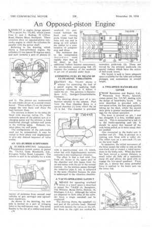
11 in patent No. 716,802, which comes from C. and J. Redrup, 25 Clifton Road, Heaton Moor, Stockport. These inventors show an opposed-piston twostroke engine in which the cylinders lie parallel with the power shaft.
Referring to the drawing, which shows a four-cylindered engine, the cylinders (1) are spaced 90 degrees apart and each contains a pair of pistons (2 and 3). The pistons are reciprocated by cam-tracks (4) cut on a central rotary barrel. Three collars (5) on the pistons engage the cam faces and share the load between them.
The mixture is drawn in via tubes (6) fitted with one-way valves (7). The underside space of the pistons acts as a charging pump and the mixture is later transferred through cylinder-wall ports to the working space. Exhaust, too, takes place via wall ports.
The configuration of the carn-tracks need not be symmetrical; it may be varied in both phase and displaCement to give any desired sequence of valve events.
AN ALL-RUBBER SUSPENSION
.1-1. A RUBBER-SPRUNG independent
suspension system comes, in patent No. 716,563, from Metalastik, Ltd., Evington Valley Road, Leicester. The scheme is said to be suitable for a wide variety of purposes from normal road vehicles to gun carriages and agricultural machinery.
As shown in the drawing, the stub axle is carried on a pair of swinging links in the well-known way. The novel feature is the use of a rubber-and-metal
sandwich (1) positioned between the fixed and moving parts. Under load the links will rise and in doing so will subject the rubber to a combination of compression and shear.
The resistance due to the compression increases more rapidly than that of the shear, so that additional buffers become unnecessary. An intermediate constraining link (2) opposes the tendency of the sandwich to get out of parallel under load.
laitimi
alannen
immigung ATOMIZING FUEL BY MEANS OF ULTRASONIC VIBRATIONS
DATENT No. 716,443 shows a
scheme for atomizing the fuel of a petrol engine by applying highfrequency vibrations to it before it meets the air. The patentee is DaimlerBenz A.G., Stuttgart-Untertiirkheim, Germany.
The drawing shows part of a carburetter adapted to the scheme. Fuel from the float chamber flows to a second chamber (1) from which the jet (2) is fed. The chamber is provided with a quartz-crystal unit (3) which, when fed with high-frequency current, converts it into mechanical vibration. The effect is that a fuel mist, free from air, forms in the upper part of the chamber and this issues from the jet and mixes with the air in the normal . manner. As the mixture passes through the induction pipe it, too, is subjected to the same vibration because the pipe is submerged in the vibration chamber.
A VALVE-OPERATING LAYOUT
A MEANS for operating overhead
valves in a small space is described in patent No. 716,828 (A. Sampietro, The Whittier, I3urns Drive, Detroit, 14, Michigan, U.S.A.). Although the valves are disposed on both sides of the cylinder head, a single camshaft can be employed.
The drawing shows the camshaft (1) and part of the cylinder head. Normal push-rods operate the valves on the left, but those on the right are worked by
secondary push-rods (2). These are moved by the primary push-rods via special rockers which have the action of bell-crank levers.
The layout is said to leave adequate space available for the inlet and exhaust passages, and economizes in overall height.
A TWO-SPEED HAND-BRAKE LEVER
L'ROM Ransomes and Rapier, Ltd., I Waterside Iron Works, Ipswich, comes patent No. 715,787, dealing with the design of hand-brake levers. The lever described is provided with a two-speed action, the first speed quickly taking up the slack, whilst the second ratio gives a greater mechanical advantage for the actual operation.
The lever is pivoted on pin 1 and has alongside it a free, toothed quadrant (2). This is connected by a rod (3) to the brake-operating arm (4). It should be noted that instead ctf the rods being pulled, as is more usual, they are pushed.
Also connected to the brake arm is another rod (5), This is pivoted to a rocking arm fitted with a roller (6). The roller runs on a cam-track (7) cut on the lever itself.
In operation, the initial movement of the lever causes the roller to ride on the cam-track and so impart a rapid move-, ment to the brake arm, When the lever has been moved a certain distance, a small roller (8) falls off a stationary ramp (9) and allows the pawl( (al) to, engage the low-speed quadrant. ' From then on, a slower but more powerful force is applied to the brake arm via the lower rod.